3-4 735/737 Feeder Protection Relay
GE Power Management
3.2 CONTROLS 3 SETUP AND OPERATION
3
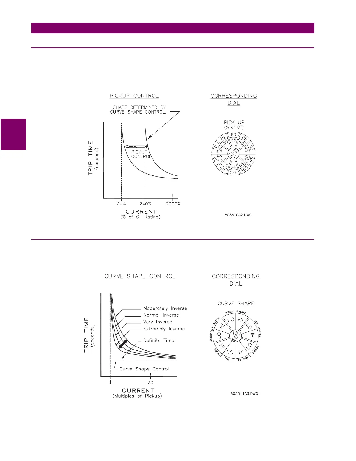
3.2.5 GROUND PICKUP [5]
For any ground curve shape and curve multiplier, the pickup current for overcurrent timeout is determined by this control. It
is set as a percentage of sensor CT rating which is the phase CTs for residual sensing or the core balance CT for zero
sequence sensing. Read the pickup current from the inner LO band when the ground CURVE SHAPE is set to a LO range
(15 to 55%). Use the outer HI band if the ground CURVE SHAPE is set to a HI range (60 to 100%). Select OFF to disable
ground time overcurrent pickup and trip.
Figure 3–6: GROUND TIME PICKUP SETTING
3.2.6 GROUND CURVE SHAPE [6]
Five different curve shapes can be selected for the ground time overcurrent to provide the required coordination. These are
definite time, moderately inverse, normal inverse, very inverse and extremely inverse. For each curve, either the LO band
or HI band of the ground pickup setting is selected. See Chapter 5 for actual curves and curve values in table form.
Figure 3–7: GROUND CURVE SHAPE SETTING