2-4 735/737 Feeder Protection Relay
GE Power Management
2.1 MECHANICAL 2 INSTALLATION
2
2.1.3 PRODUCT IDENTIFICATION
Product attributes will vary according to the configuration and options installed based on the customer order. Before apply-
ing power to the relay, remove the relay by pulling up on the handle. Examine the labels on the unit and check that the cor-
rect options are installed.
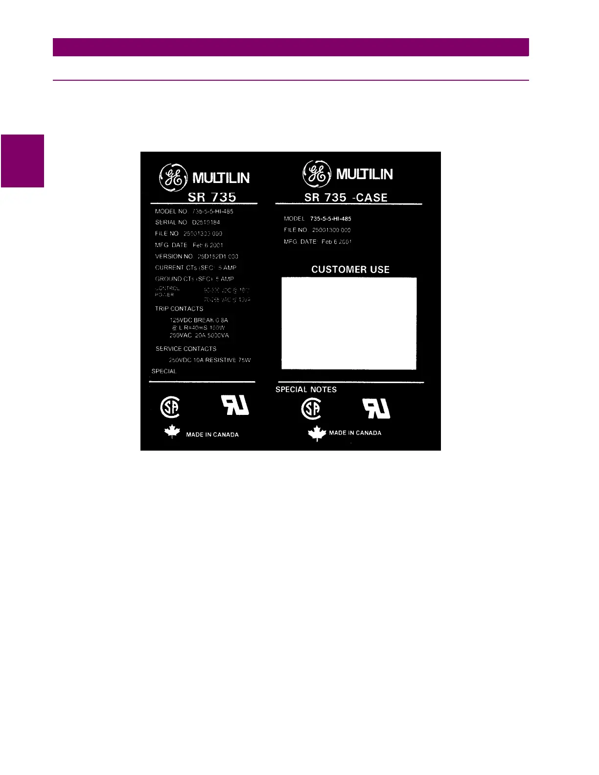
The following section explains the information included on the labels.
Figure 2–7: 735 LABELS
1. MODEL NO: The model number shows the configuration of the relay including phase CTs, ground CT, power supply
voltage and communications.
2. SERIAL NO: This is the serial number of the relay.
3. FILE NO: This number indicates the configuration of the relay. It is important when inserting a relay into a case to
ensure that the configuration file number is the same for both pieces. See Section 1.2.3: REVISION HISTORY on page
1–5 for details.
4. MFG DATE: This is the date the relay was produced at the factory.
5. VERSION NO: This indicates the revision of the firmware installed in the relay.
6. CURRENT CTs: This indicates whether the phase CTs installed are 5 A or 1 A.
7. GROUND CT: This indicates whether the ground CT installed is 5 A or 1 A.
8. CONTROL POWER: This indicates the power supply input configuration installed in the relay.
9. TRIP & SERVICE CONTACTS: This section gives a brief description of the relay contacts. For a more detailed descrip-
tion, see Section 1.3.3: OUTPUTS on page 1–7.