2-10 735/737 Feeder Protection Relay
GE Power Management
2.2 ELECTRICAL 2 INSTALLATION
2
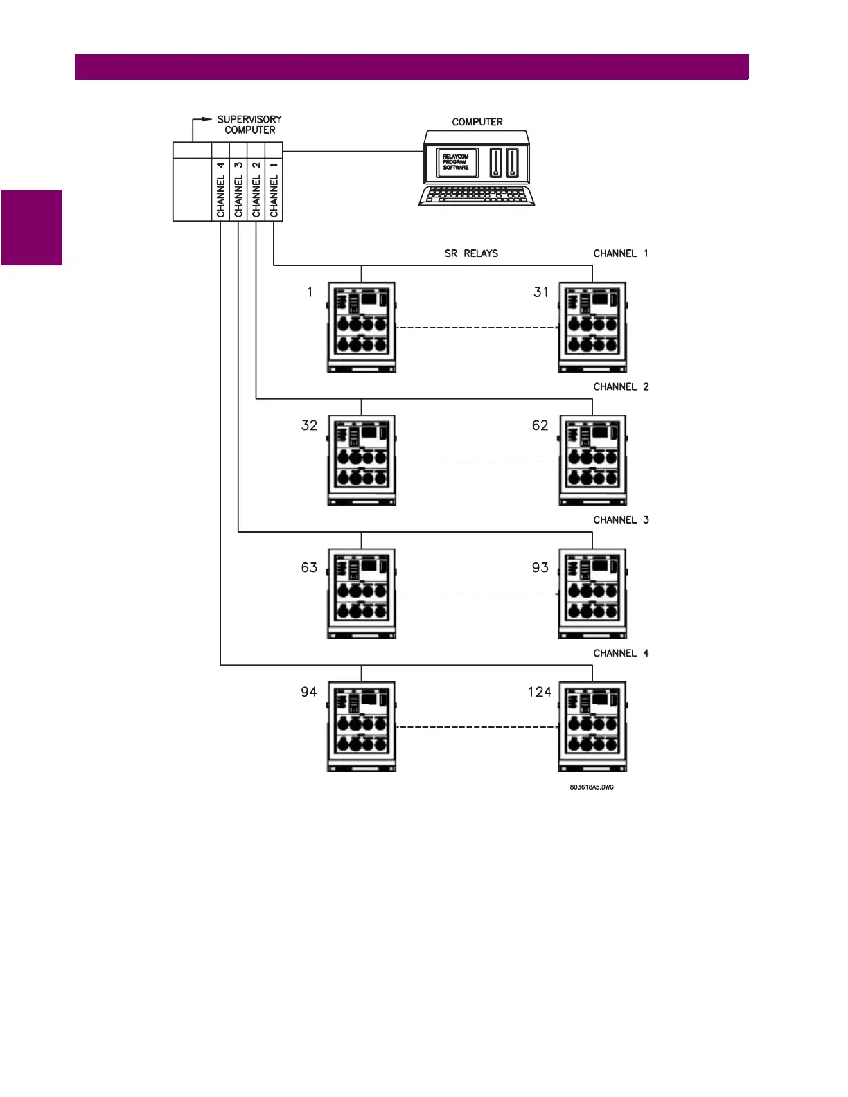
Figure 2–13: 4 CHANNEL, 124 RELAY SYSTEM
If the communications option is used, a disk with the
735SETUP.EXE
software (
737SETUP.EXE
for the 737) is provided.
When a PC running this program is connected to the 735/737, actual values and settings can be read and printed and relay
operation can be simulated for training/testing purposes. To use this software, the computer RS232 serial port is connected
through an RS232 to RS485 converter as shown below. This can be a commercially available model or the GE Power Man-
agement RS232/RS485 converter module. Set the relay front panel communication switches to 9600 baud, address 1, test
ON. Apply power to the computer, RS232/ RS485 converter, and relay. Install the setup disk in a personal computer and
type "
A:735SETUP
" ("
A:737SETUP
" for the 737) to run the software. See Section 3.5: SETUP PROGRAM on page 3–11
for an explanation of menu items and program operation.