GFK-1322A Chapter 4 Configuring the LBIM 4-3
4
Note
Care should be taken to assure proper orientation or direction of variables
defined. An input device such as a temperature sensor will send the value to the
network as an output network variable. That network variable would then be
declared as an input to the LBIM and be mapped into an input register within
the PLC.
Step B. Using the configuration utility software, assign network variable types to the LBIM and
the registers in the PLC memory space to which the variable types will map
a45644
CPU
Re
1
Re
2
Re
3
Re
4
Re
5
Re
6
Re
7
Re
8
Re
9
Re
10
Re
11
Re
12
Re
13
SNVT_temp
SNVT_count
SNVT_freq_f
SNVT_temp
SNVT_temp_f
PLC LonWorks BIM
SNVT_temp
SNVT_temp
SNVT_count
displa
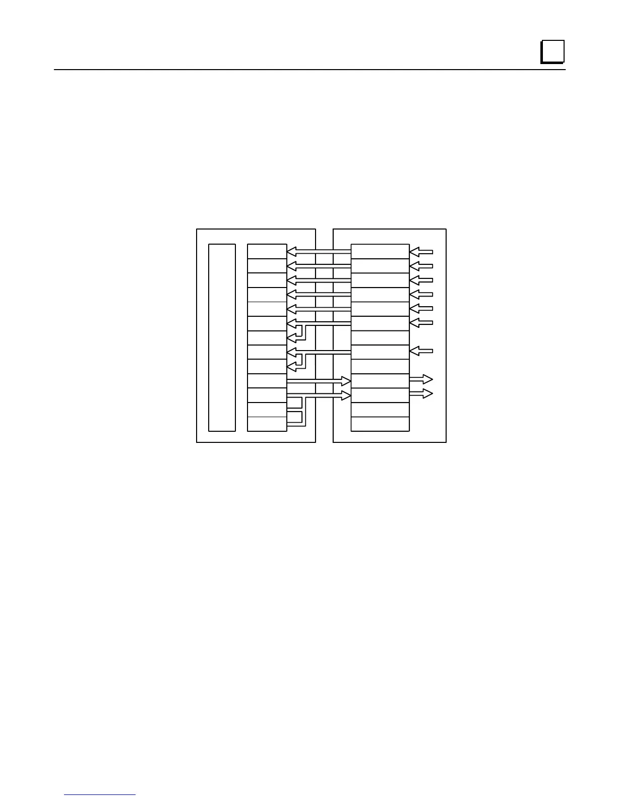
Figure 4-2. Example: Assigning Network Variables Types to the LBIM and PLC Registers
In the example illustrated in Figure 4-2, SNVT_temp and SNVT_count network variable types are
one-word values that map directly into a single register address. SNVT_freq_f and SNVT_temp_f
are double word values that map into two register locations. The type
display
is a three-word user-
defined network variable that maps into three register locations.
At this point, the module mapping is defined, but the actual network variables are not yet bound
to the module and the module is also not configured with the L
ON
W
ORKS
network image. (See
“Binding Network Variables.”)

 Loading...


