4-10 Series 90™-30 PLC LONWORKS® Bus Interface Module User's Manual
–
June 1997 GFK-1322A
4
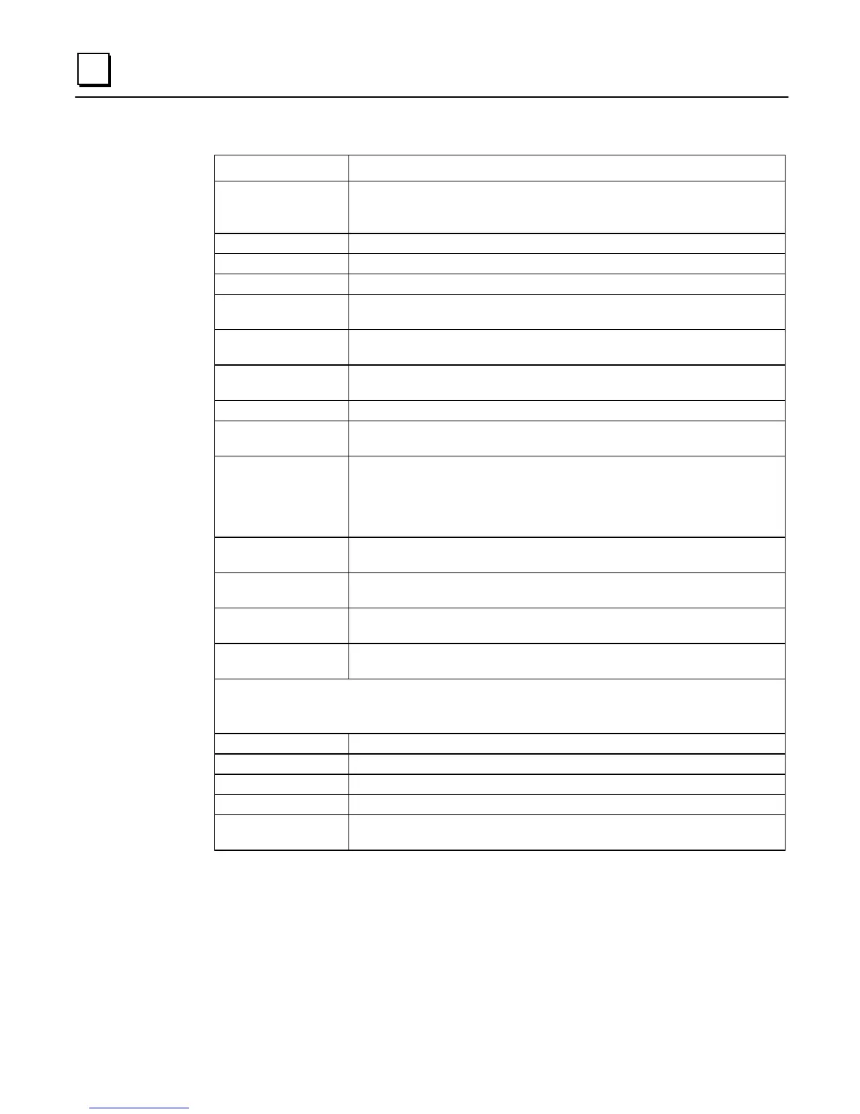
Table 4-1. Configuration Editor Fields
Field Description
Program ID L
ON
W
ORKS
Program ID. Same as the Configuration Name. To change, type up to
8 characters in the field (7 characters maximum recommended) and press
E
NTER
.
CPU PLC CPU Model Number. To change, click on arrows to scroll through choices.
Transceiver Transceiver Type. Use pull down menu to view choices.
Max Size (4 fields) Maximum number of register references allowed in this configuration.
Entries Number of Variable entries defined for the reference space. This is a display-
only field.
Start Addr Beginning reference for the register. To change, highlight the current value and
type in a new reference address.
Reserved Number of reserved reference locations. The reserved locations will occupy the
lowest address locations.
Length Length or number of references currently configured.
Usage Graphical representation of the configured portion of the reference space as a
portion of the maximum allowed space.
Valid Bit End Addr Reference address of the beginning of the valid bit space. Valid bits are stored in
the %I space and are assigned automatically beginning at this address and grow
down as more are defined. Change this field by highlighting the current value
and entering a new value. Note that the current valid bit configuration may need
to updated manually to affect this change.
Defaults Default size parameters. Activating this command allows the user to set default
values for the maximum sizes allowed for the various CPU choices.
Module Rep Print Module Report. Activating this command prints a report to the system
printer showing the configuration details.
Save Cfg Save configuration. Activating this command saves the current configuration to
the file.
Cancel Cancel. Activating this command returns control to the register configuration
screen without saving any changes since the last save.
Node Object Network Variable Names
The LBIM implements a standard Node Object as specified in the L
ON
M
ARK
Interoperability Guidelines.
You can configure the names of the standard network variables for this object.
nviObjRequest The name of the Object Request (SNVT_obj_request, index 0) network variable.
nvoObjStatus The name of the Object Status (SNVT_obj_status, index 1) network variable.
nviFileRequest The name of the File Request (SNVT_file_req, index 2) network variable.
nvoFileStatus The name of the File Status (SNVT_file_status, index 3) network variable.
SCPT_max_snd_t Configuration parameter for Maximum Send Time. Set value by Selecting
current value and type in new value.

 Loading...


