C-4 Series 90™-30 PLC LONWORKS® Bus Interface Module User's Manual
–
June 1997 GFK-1322A
C
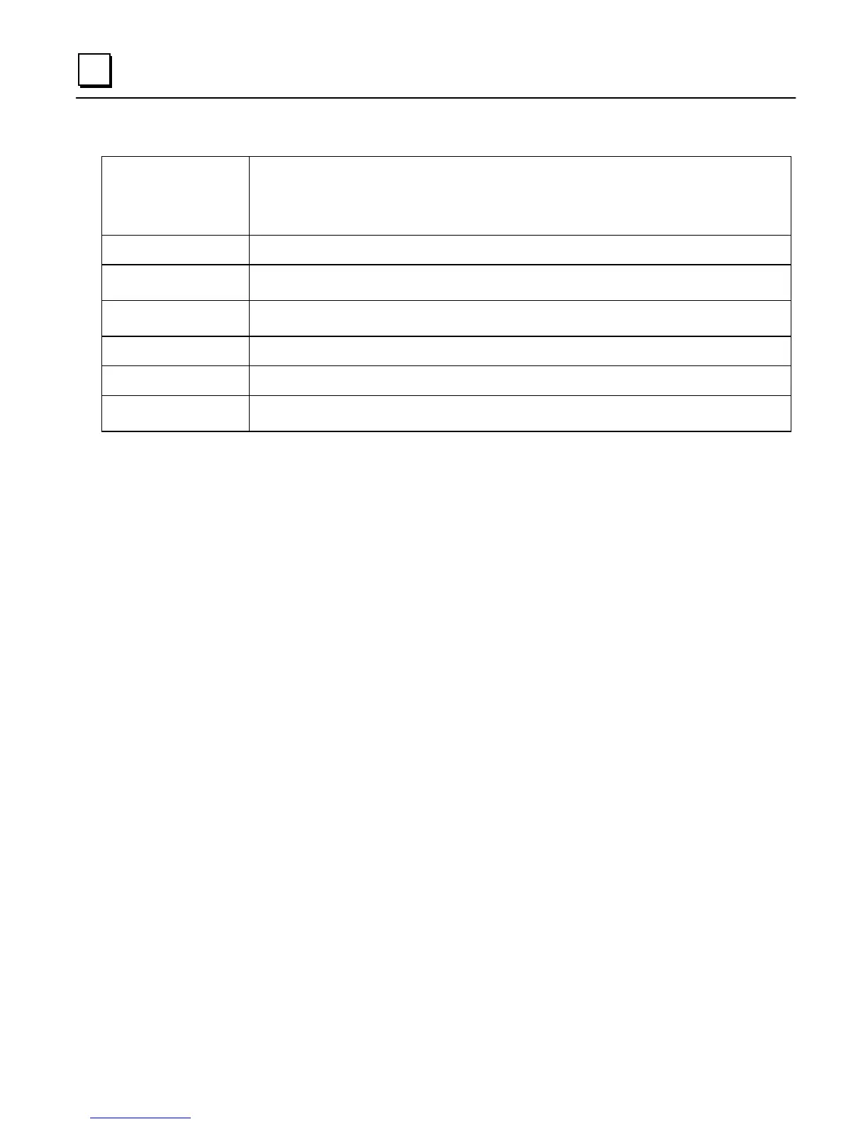
Table C-5. - Continued
Module Control %Q
locations
8 bits of %Q register (mapped to first location).
Bit 1: Reset Module (hardware reset)
Bit 2: Send Service Pin Message
Bits 3-8: reserved for future use.
Parameter 0 definition Created from Network Variable Definition File (.XIF) file.
Config File/Init File
definition
Created from Network Variable Definition File (.XIF) file.
Hand Held Programmer By setting the maximum parameter to 1, and parameter 1 to the text "Last Parameter", the API will
handle all commands from the Hand Held Programmer attached to the PLC CPU
Dependent parameters None (API skip table not used).
Configuration Freeze Not Used
Packing of Discrete NVs
into %I, %Q
SNVT_lev_disc, SNVT_switch supported.
Configuration Parameter Types
Standard Configuration Parameter Types (SCPTs) are used to transfer node configuration
information via the L
ON
T
ALK
File Transfer protocol. SCPTs provide a means of handling large
amounts of configuration information on a node. SCPTs do not use network variable resources
and are downloaded and uploaded to a node via the L
ON
T
ALK
file transfer protocol.

 Loading...


