Unit Size Terminal Torque Bolt size
41, 42, 43 and 44 Mains
Motor
19 Nm (168 in-lbs) M10
Load sharing
Brake
9.5 (84 in-lbs) M8
51 and 52 Mains
Motor
Load sharing
19 NM (168 in-lbs) M10
Brake 9.5 (84 in-lbs) M8
61, 62, 63 and 64 Mains
Motor
19 Nm (168 in-lbs) M10
Load sharing
Brake
Regen
19 Nm (168 in-lbs)
9.5 Nm (84 in-lbs)
19 Nm (168 in-lbs)
M10
M8
M10
Table 3.1: Torque for terminals
3.1.6 Shielded Cables
It is important that shielded and armoured cables are connected in a proper way to ensure high EMC immunity and low emissions.
Connection can be made using either cable glands or clamps:
• EMC cable glands: Generally available cable glands can be used to ensure an optimum EMC connection.
• EMC cable clamp: Clamps allowing easy connection are supplied with the frequency converter.
3.1.7 Motor cable
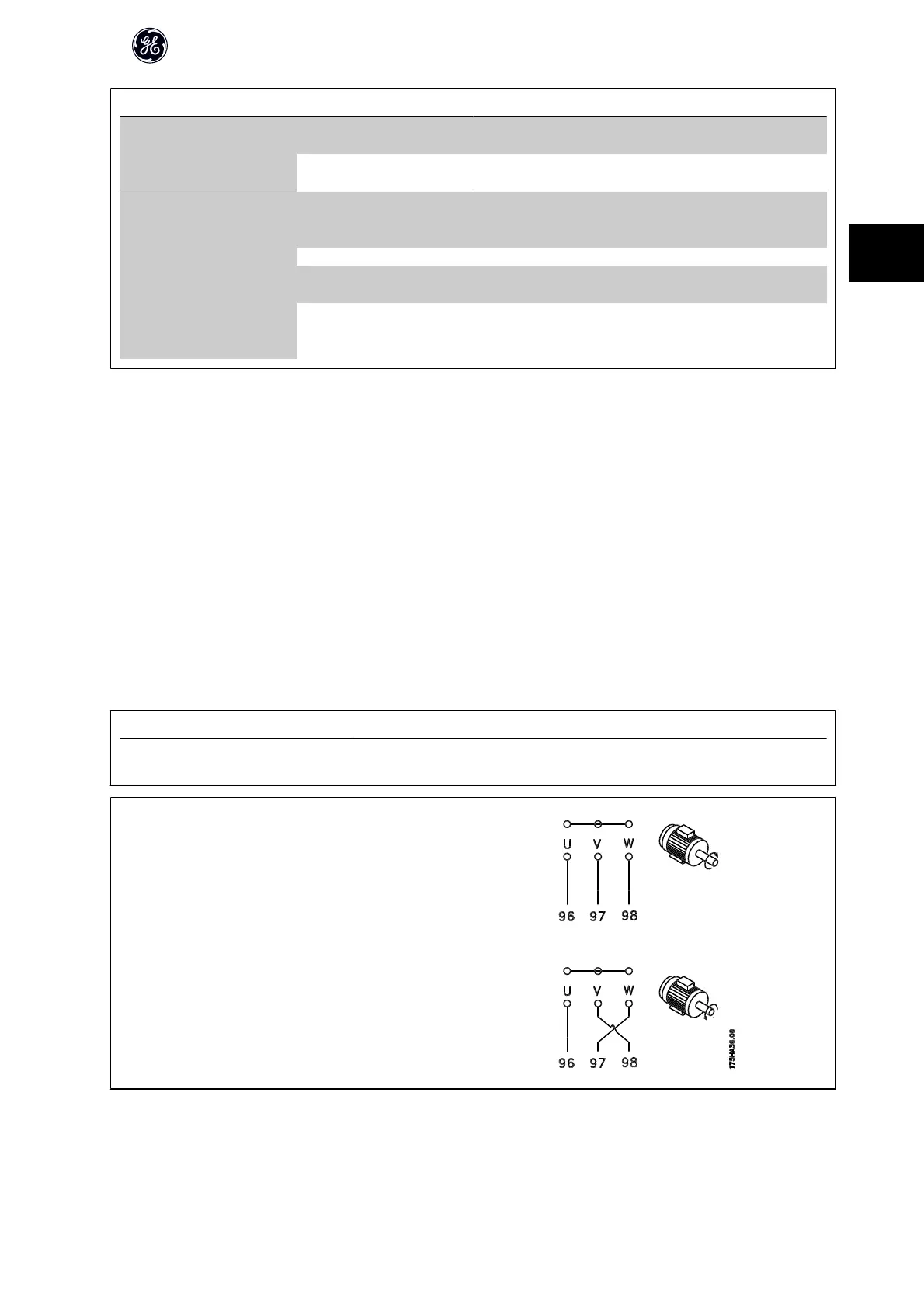
The motor must be connected to terminals U/T1/96, V/T2/97, W/T3/98. Earth to terminal 99. All types of three-phase asynchronous standard motors can be used
with a frequency converter unit. The factory setting is for clockwise rotation with the frequency converter output connected as follows:
Terminal No.
Function
96, 97, 98, 99 Mains U/T1, V/T2, W/T3
Earth
• Terminal U/T1/96 connected to U-phase
• Terminal V/T2/97 connected to V-phase
• Terminal W/T3/98 connected to W-phase
The direction of rotation can be changed by switching two phases in the motor cable or by changing the setting of par. H-08 Reverse Lock.
Motor rotation check can be performed using par. P-08 Motor Rotation Check and following the steps shown in the display.
AF-600 FP High Power Operating Instructions
21
3