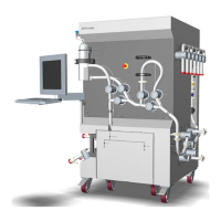
Components on system — outlet
s
ide
The illustration below shows the location of components on the outlet side of the
system. The system is shown without flow kit.
Part Component ID tag Function
21 Cable for
c
onnection
to air sensor
AE-152 A cable connection to air sensor AE-152
that is prefitted on the flow kit.
22 Column
valves
XV-031
to
XV-035
A five-valve assembly for column bypass/
inline/up flow, and down flow.
23 Sensor plug
for pressure
sensor
PE-113 Pressure sensor plug for the communica-
tion cable for pressure sensor PE-113 that
is prefitted on the flow kit.
24 Flow meter FE-141/
FT-141
A flow meter FE-141 which measures flow
using magnetism.
3 System description
3
.2 Illustrations
38
ÄKTA ready XL Operating Instructions 29281616 AE
*** TeDIS Valid on Date Printed Printed on: 15-09-2023 11:27:35 ***

 Loading...