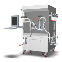
Components on system — back
T
he illustration below shows the location of components on the back of the system.
The system is shown without flow kit.
Part Function
28 Inlet for lower cooling units
29 Outlet for upper cooling unit
30 System electrical cabinet door
3 System description
3
.2 Illustrations
40
ÄKTA ready XL Operating Instructions 29281616 AE
*** TeDIS Valid on Date Printed Printed on: 15-09-2023 11:27:35 ***

 Loading...