3 Installation
26 GE Healthcare 32551-IMG rev 6
7 Attach the upper cover after all adjustments have been completed.
CAUTION!
It is strongly recommended that you check all the connectors again to
prevent power-on problems.
8 Hang the c-arm to the axle assembly so that the motor enters the
axle.
NOTE!
Be careful not to damage: 1. The motor, 2. The metal plate sticking out of
the ECS mechanism or 3. Microswitch placed on the side of the ECS
mechanism.
9 Tighten the top two bolts to the c-arm and fix the remaining four
bolts.
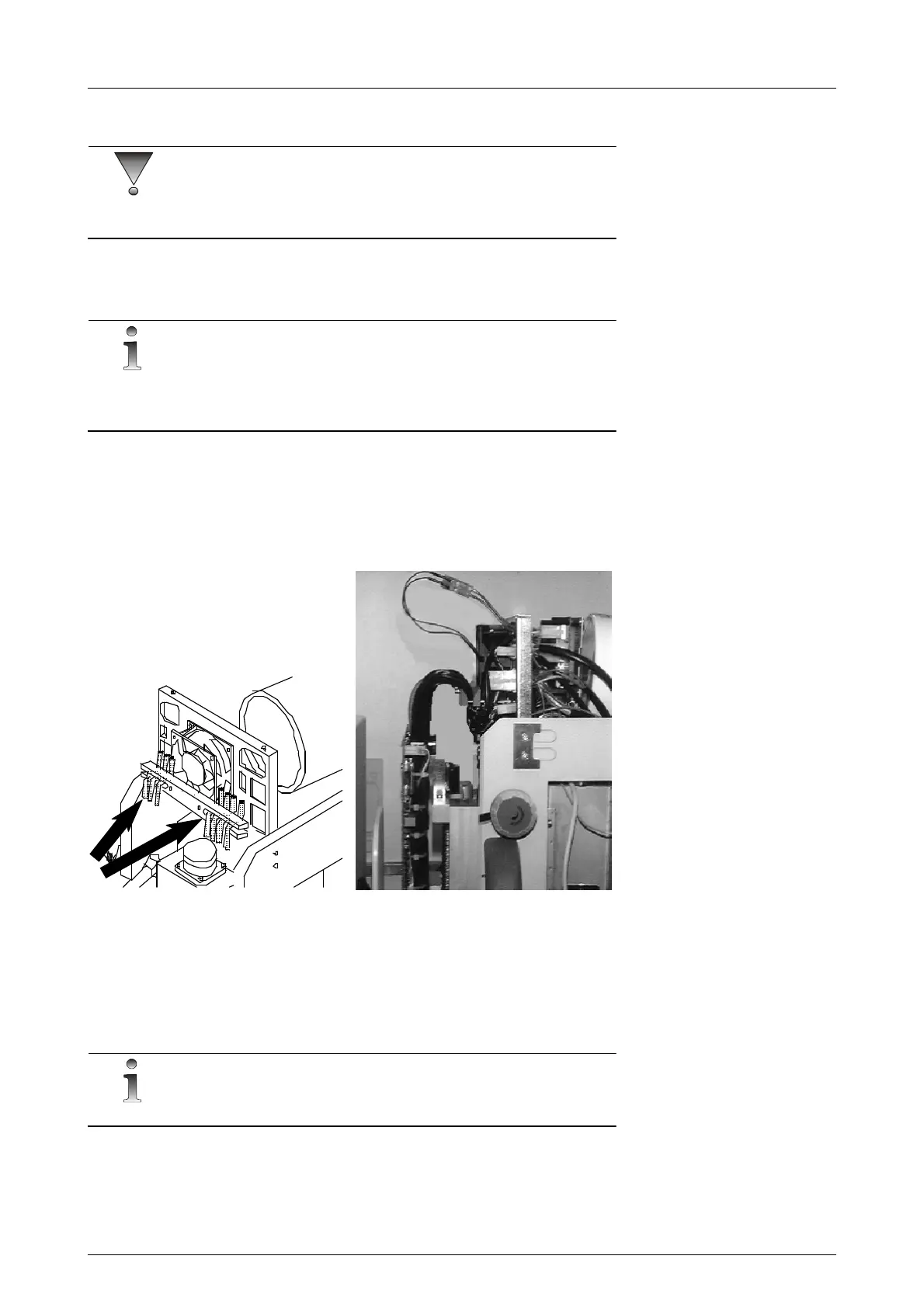
10 Close the connectors to the c-arm. Check that the bracket relieves
stress to the wires in the connectors. See figure 3.9, Securing the
cables to the c-arm.
Fig 3.9. Securing the cables to the c-arm
11 Make sure that the metal plate going through the slots of the optical
interrupters on the ECS Driver Board is correctly positioned and that
there are no cables entering its pathway when the c-arm moves.
3.6 ATTACHMENT OF THE CONTROL PANEL
NOTE!
If the Alpha ID is used, please read the separate manual.
The base of the control panel is attached on the right side of the unit. If
desired, the base can be moved to the other side of the unit or attached to
a wall. See Figure 3.10, Control panel attachment.