Parts lists, drawings and replacement
2001989-203C ApexPro™ Telemetry 7-13
022A
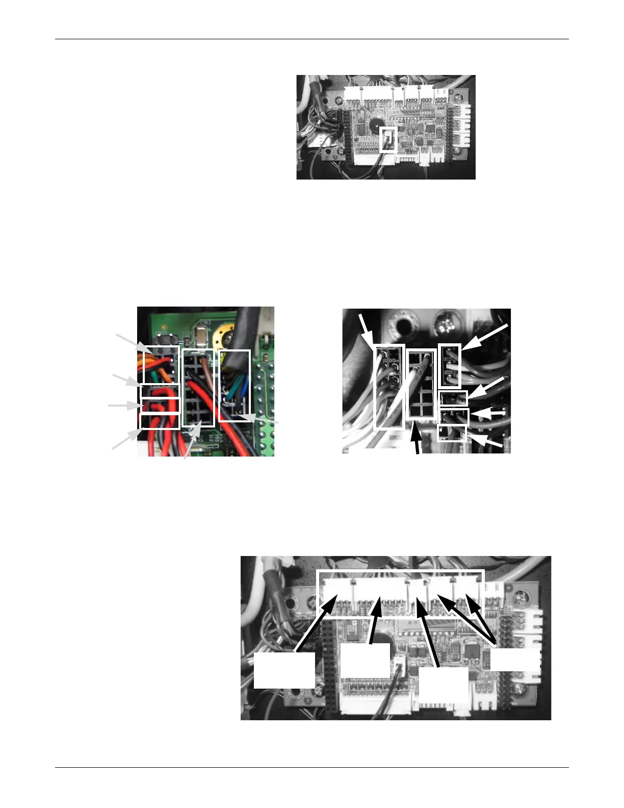
9. Disconnect the LAN, RS232 serial port, CPU interface card, power switch, reset,
and watchdog timer connectors from the connection block near the back edge of
the SNMP connection board. Note the position and orientation of the connectors
for reassembly.
259A & 057A
10. Disconnect the temperature sensor, network port, power fail input, and fan
connectors from the receptacles along the right edge of the SNMP connection
board. Note the position and orientation of the connectors for reassembly.
022A
CPU card
interface
connector
LAN Connector
CPU card
interface
connector
Watchdog
timer
connector
RS232 Serial Port Connector
PN 2021512-009
PN 2021512-017/2021512-021
LAN
connector
Power
switch
connector
Reset
connector
Watchdog
timer
connector
Power
switch
connector
Reset
connector
RS232 Serial Port Connector
Power fail
input
connector
Temperature
sensor
connector
Network
port
connector
Fan
connectors