7-26 ApexPro™ Telemetry 2001989-203C
Parts lists, drawings and replacement
098A
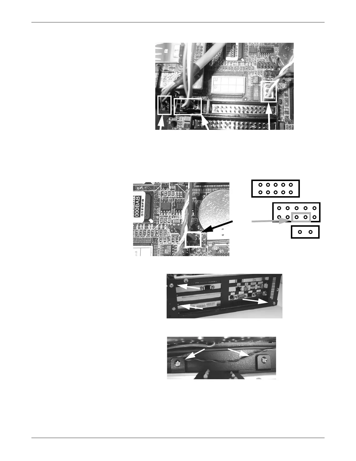
7. Disconnect the watchdog timer from the receptacle near the back left corner of
the main CPU board. Note the pin position and orientation of the watchdog timer
connector for reassembly.
099A, 100A
8. Remove the 3 screws securing the back of the CPU module to the chassis.
046A
9. Remove the 2 screws securing the front of the CPU module to the chassis.
048A
10. Carefully move the CPU module far enough to allow card removal.
11. Using a phillips screwdriver, remove the 2 screws securing the USB/mouse/
Unity Network MC network ports and the back of the main CPU board in the
CPU module.
USB
connector
Serial port
connector
ATX connector
Watchdog
timer
connector