Control or Measure Parameter
© 2017 General Electric Company – All Rights Reserved. ADTS 405 R/F Mk2 Instruction Manual-English | 29
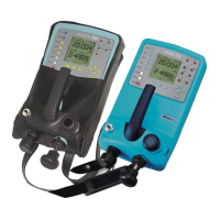
Figure 4-3: Triple Display
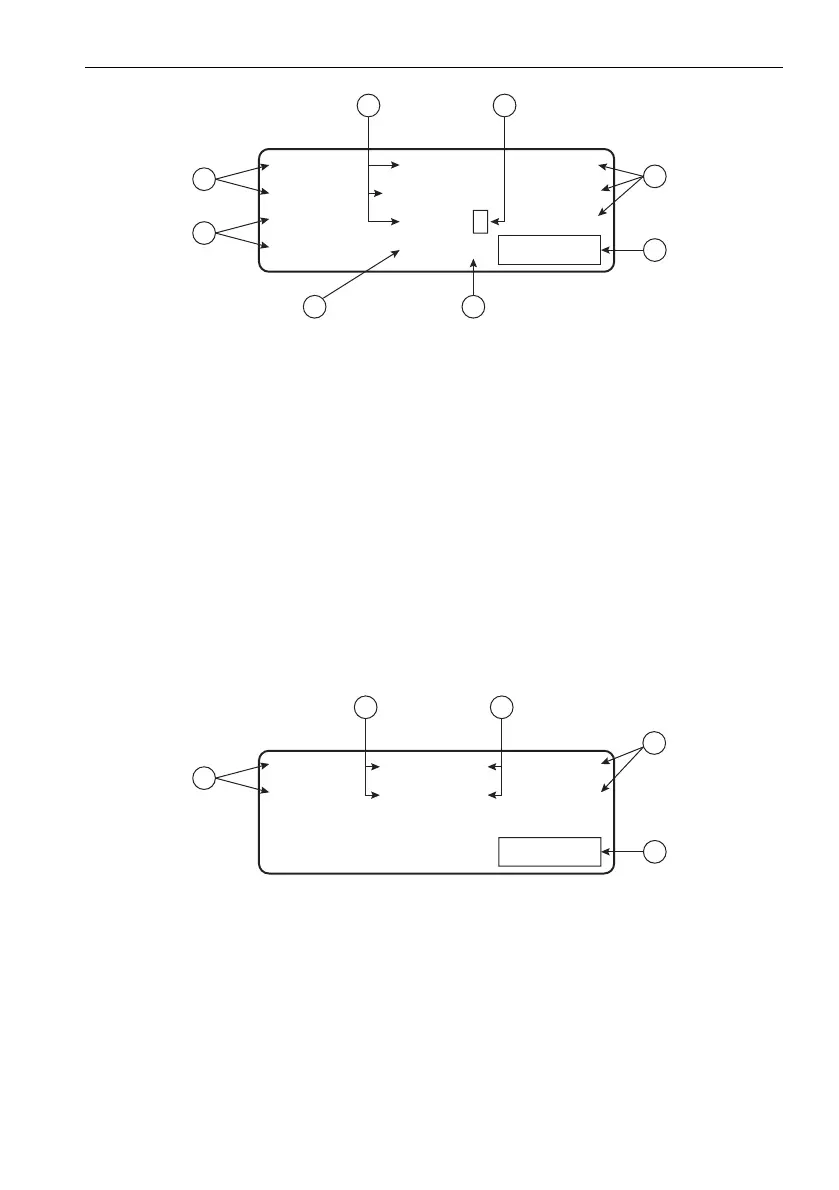
4.1.2 Rate Timer Displays
When in Leak Measure mode and, after completing a rate timing, the system generates the
rate timer displays. These displays are independent of the display mode (single, dual, triple or
option).
Note: There is no pointer for the primary parameter, values cannot be entered in the rate
timer displays.
Pressing a parameter key (ALT, ROC, etc) or CLEAR/QUIT exits the rate timer displays.
Figure 4-4: Rate Timer Display - Aeronautical Units
1 Constant indication of values. 2 Measured value.
3 “T” for timed rate of change. 4 Units of measurement.
5 Special messages, e.g. warm-up
period.
6 “<” Pointer for parameter, i.e. aim that
changes on data entry.
7 Aim (set-point or target) in control
mode, or “Leak Measure” when the
pressure controller is off.
8 Current changing parameter.
1 Measured parameter. 2 Measured value.
3 “T” for timed rate of change. 4 Units of measurement.
5 Special messages, e.g. warm-up
period.
Alt 1228 ft
CAS = 300.0 kts
ROC 2995 ft/m
Aim 3000< WARMUP
1
2
4
3
5
67
8
ROC -1.00T ft/m
RtCA -0.10T kts/m
Timed Rates WARMUP
2
4
3
5
1
 Loading...