Chapter 2. Installation
12 | ADTS 405 R/F Mk2 Instruction Manual-English © 2017 General Electric Company – All Rights Reserved.
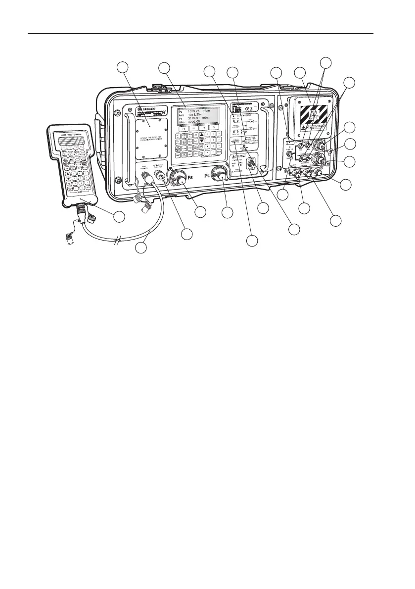
2.5 Product Views
Figure 2-4: ADTS 405F Mk2 General View
1 Cover plate for communications
option
2 Keypad and display
3 Solenoid valve status indicator 4 System status indicator
5 Elapsed time indicator 6 Fan outlet cover
7 DC power supply fuses (optional) 8 AC power supply fuses
9 DC power supply connector (optional) 10 Cross bonding connector
11 AC power supply connector 12 Vacuum input connector
13 Auxiliary vacuum output connector 14 Pressure input connector
15 Pump power supply switch 16 Calibration enable switch
17 Power supply switch 18 Altitude sensor datum height (altitude
reference level)
19 Pitot output connector 20 Static output connector
21 Altitude encoder connector (optional) 22 Hand terminal cable
23 Remote hand terminal
1
2
3
4
5
6
7
8
9
10
11
12
13
14
15
16
17
18
19
20
21
22
23
 Loading...