B-20 F60 Feeder Protection System GE Multilin
B.4 MEMORY MAPPING APPENDIX B
B
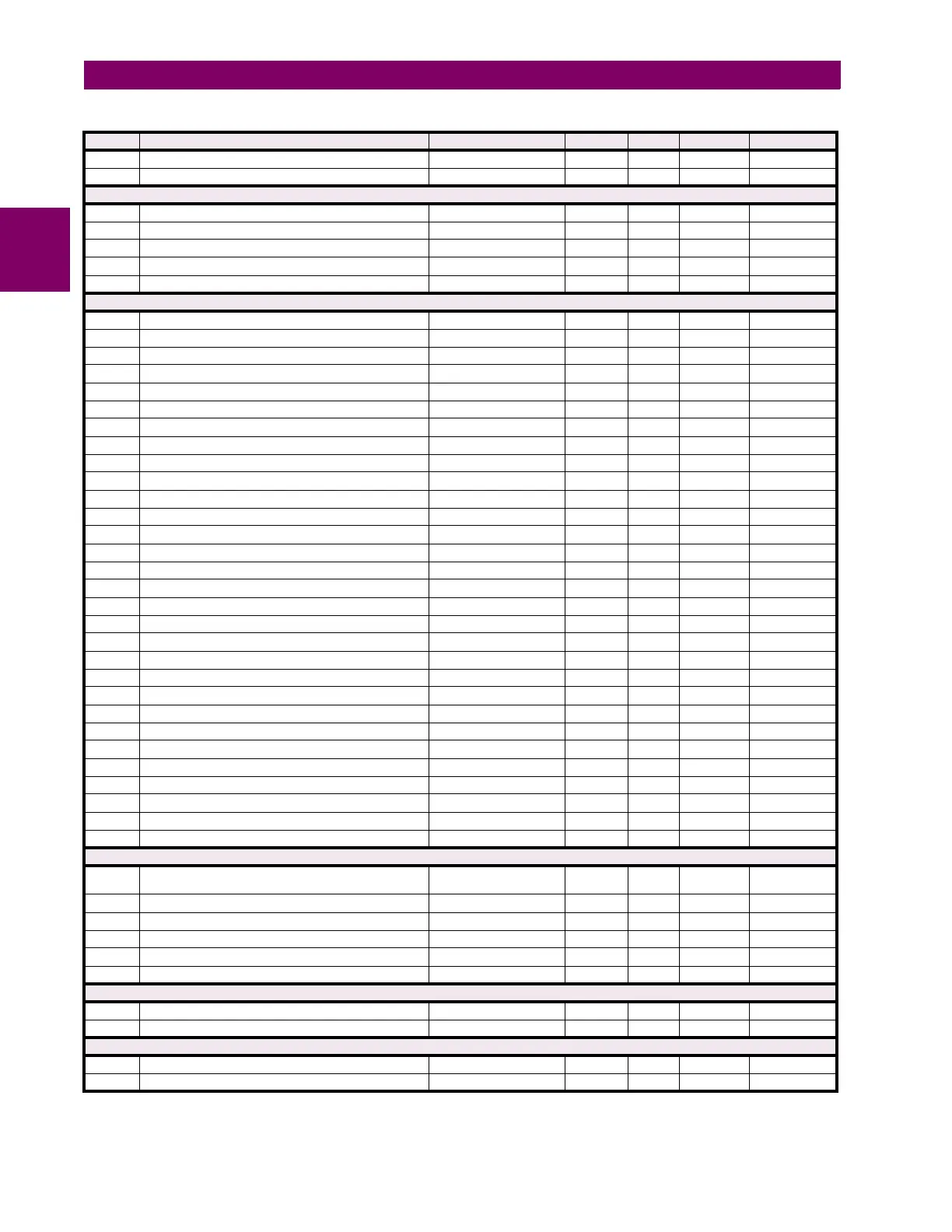
2266 ...Repeated for Hi-Z Capture 3
2269 ...Repeated for Hi-Z Capture 4
Hi-Z (High Impedance Fault Detection) RMS Records (Read Only) (4 modules)
2270 Hi-Z RMS Capture 1 Trigger Type 0 to 6 --- 1 F188 0 (NONE)
2271 Hi-Z RMS Capture 1 Time 0 to 1 --- 1 F050 0
2273 ...Repeated for Hi-Z RMS Capture 2
2276 ...Repeated for Hi-Z RMS Capture 3
2279 ...Repeated for Hi-Z RMS Capture 4
Fault Location (Read Only) (5 modules)
2340 Fault 1 Prefault Phase A Current Magnitude 0 to 999999.999 A 0.001 F060 0
2342 Fault 1 Prefault Phase A Current Angle -359.9 to 0 degrees 0.1 F002 0
2343 Fault 1 Prefault Phase B Current Magnitude 0 to 999999.999 A 0.001 F060 0
2345 Fault 1 Prefault Phase B Current Angle -359.9 to 0 degrees 0.1 F002 0
2346 Fault 1 Prefault Phase C Current Magnitude 0 to 999999.999 A 0.001 F060 0
2348 Fault 1 Prefault Phase C Current Angle -359.9 to 0 degrees 0.1 F002 0
2349 Fault 1 Prefault Phase A Voltage Magnitude 0 to 999999.999 V 0.001 F060 0
234B Fault 1 Prefault Phase A Voltage Angle -359.9 to 0 degrees 0.1 F002 0
234C Fault 1 Prefault Phase B Voltage Magnitude 0 to 999999.999 V 0.001 F060 0
234E Fault 1 Prefault Phase B Voltage Angle -359.9 to 0 degrees 0.1 F002 0
234F Fault 1 Prefault Phase C Voltage Magnitude 0 to 999999.999 V 0.001 F060 0
2351 Fault 1 Prefault Phase C Voltage Angle -359.9 to 0 degrees 0.1 F002 0
2352 Fault 1 Phase A Current Magnitude 0 to 999999.999 A 0.001 F060 0
2354 Fault 1 Phase A Current Angle -359.9 to 0 degrees 0.1 F002 0
2355 Fault 1 Phase B Current Magnitude 0 to 999999.999 A 0.001 F060 0
2357 Fault 1 Phase B Current Angle -359.9 to 0 degrees 0.1 F002 0
2358 Fault 1 Phase C Current Magnitude 0 to 999999.999 A 0.001 F060 0
235A Fault 1 Phase C Current Angle -359.9 to 0 degrees 0.1 F002 0
235B Fault 1 Phase A Voltage Magnitude 0 to 999999.999 V 0.001 F060 0
235D Fault 1 Phase A Voltage Angle -359.9 to 0 degrees 0.1 F002 0
235E Fault 1 Phase B Voltage Magnitude 0 to 999999.999 V 0.001 F060 0
2360 Fault 1 Phase B Voltage Angle -359.9 to 0 degrees 0.1 F002 0
2361 Fault 1 Phase C Voltage Magnitude 0 to 999999.999 V 0.001 F060 0
2363 Fault 1 Phase C Voltage Angle -359.9 to 0 degrees 0.1 F002 0
2364 Fault 1 Type 0 to 11 --- 1 F148 0 (NA)
2365 Fault 1 Location based on Line length units (km or miles) -3276.7 to 3276.7 --- 0.1 F002 0
2366 ...Repeated for Fault 2
238C ...Repeated for Fault 3
23B2 ...Repeated for Fault 4
23D8 ...Repeated for Fault 5
Synchrocheck Actual Values (Read Only) (4 modules)
2400 Synchrocheck 1 Delta Voltage -1000000000000 to
1000000000000
V1F060 0
2402 Synchrocheck 1 Delta Frequency 0 to 655.35 Hz 0.01 F001 0
2403 Synchrocheck 1 Delta Phase 0 to 359.9 degrees 0.1 F001 0
2404 ...Repeated for Synchrocheck 2
2408 ...Repeated for Synchrocheck 3
240C ...Repeated for Synchrocheck 4
Autoreclose Status (Read Only) (2 modules)
2410 Autoreclose 1 Count 0 to 65535 --- 1 F001 0
2411 Autoreclose 2 Count 0 to 65535 --- 1 F001 0
Field Unit Raw Data Settings (Read/Write Setting)
2460 Field Raw Data Port 0 to 7 --- 1 F244 6 (H1a)
2461 Field Raw Data Freeze 0 to 1 --- 1 F102 0 (Disabled)
Table B–10: MODBUS MEMORY MAP (Sheet 12 of 70)
ADDR REGISTER NAME RANGE UNITS STEP FORMAT DEFAULT