– 22 –
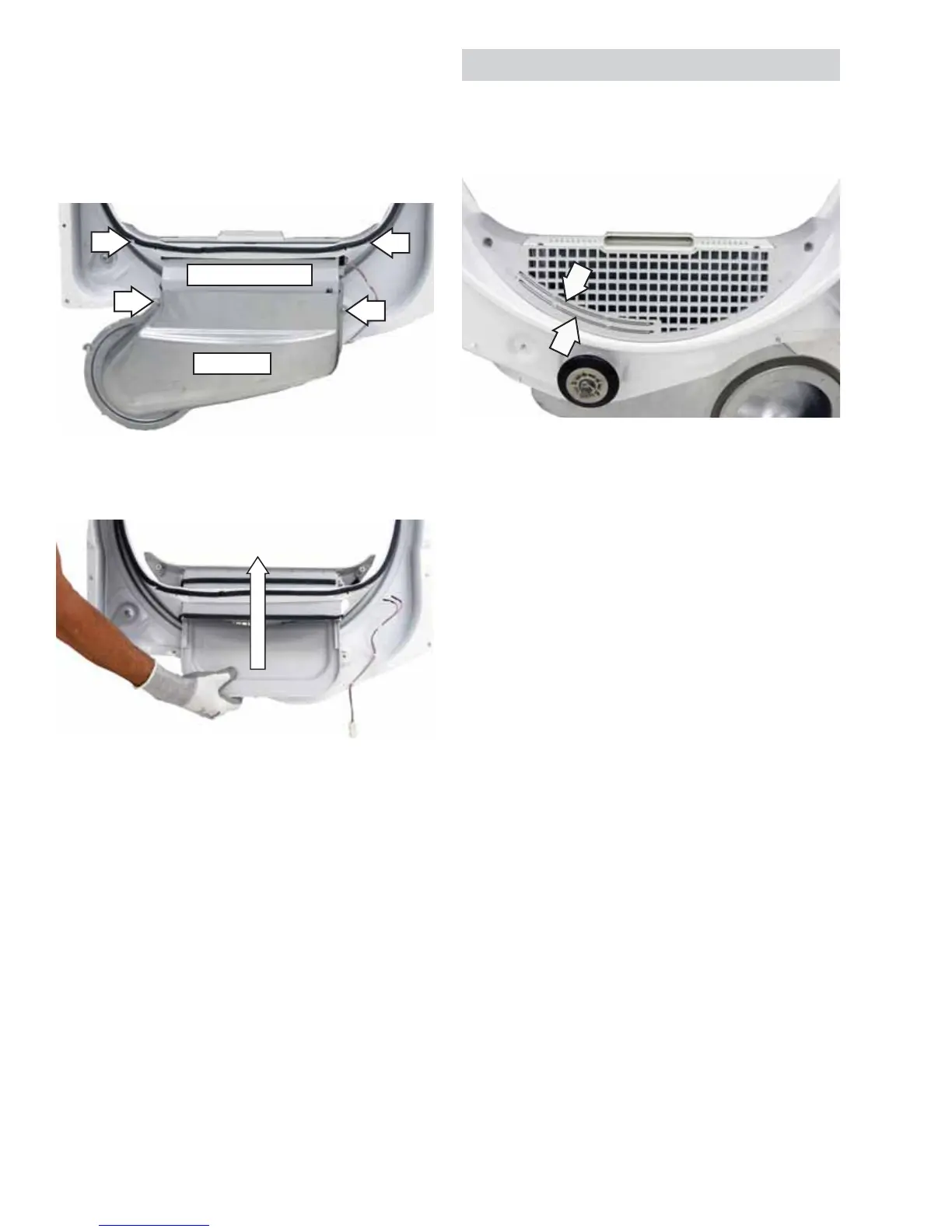
4. Remove the 2 Phillips-head screws from the
metal duct.
5. Pull the metal duct off the lint fi lter housing.
6. Remove the 2 Phillips-head screws from the lint
fi lter housing.
7. Lift the lint fi lter housing and remove it from the
front bulkhead.
8. Remove the 9/16-in. hex nut that attaches the
shaft to the front bulkhead.
To remove the drum roller shaft from the rear
bulkhead:
1. Remove the drum. (See
Drive Belt and Drum.)
2. For front service, tilt the bottom of the rear
bulkhead inward from the dryer frame (See
Rear
Bulkhead.), or remove the back panel for rear
service. (See
Back Panel.)
3. Remove the 9/16-in. hex nut that attaches the
drum roller shaft to the rear bulkhead.
Metal Duct
Lint Filter Housing
Note: The 2 sensor rods in the front bulkhead are
not replaceable. To replace the sensor rods, replace
the lint fi lter housing. (See Drum Rollers.)
• The sensor rods are connected to the
main control board. The rods are spaced
approximately 1/2 inch apart, creating an open
circuit to the control.
• The control board utilizes a low-voltage
capacitor that charges to approximately 5 VDC
when the circuit is open and discharges to less
than 1 VDC when the circuit is shorted.
• When wet clothes tumble across the 2 rods, the
clothes create a very low resistance between
the rods, discharging the capacitor.
• As the clothes become dry, their resistance
value increases and the charge across the
capacitor builds to approximately 5 VDC.
• Proper leveling of the dryer is vital for accurate
sensor drying. If the front of the dryer is raised
too high, clothes will tumble toward the rear of
the drum, preventing contact with the sensor
rods. This could produce a false dryness reading.
Moisture Sensor
The moisture-sensing circuit consists of 2 sensor
rods. They are mounted beneath the lint fi lter on the
drum side of the front bulkhead.