EasyManua.ls Logo

GE GHDS830EDWS User Manual

GE GHDS830EDWS
54 pages
To Next Page IconTo Next Page
Page #1 background imageLoading...
Page #1 background image
GE Appliances
General Electric Company
Louisville, Kentucky 40225
31-9228
GE CleanSpeak™
Dryers
Technical Service Guide
December 2012
GE Appliances
ESTIMA
TED
TOTA
L CYCLE TIME
DELAY
DRY
DAMP
CLEAN
LINT FIL
T
ER
DRYING
COOL
DOWN
Energy Smart
50 ~ 60
Extra Dry
Less Dry
70 ~ 80
90 ~ 99
30 ~ 40
10 ~ 20
More Dry
Dry
Damp
No Heat
High
Low
Medium
Extra Low
Time TempLevel
Damp
Alert
Delay
Dr
y
Extended
Tumble
Rack
Dry
Dry
Mixed Loads
No Heat
Permanent Press
Use Timed Dry
Cycles Only
Hold 3 seconds
to CANCEL
Quick Dry
Active Wear
Casuals
Quick Flu
Delicates
Jeans
Bulky Items
Timed Dry
Normal
Cottons
Sanitized
STEAMselect
Towels / Sheets
Select Steam Cycle and PUSH “STEAMselect” for garment amount
1 to2 3 to5 6 to7 8 to13
Steam Refresh
Steam Dewrinkle
Good Bes
t
monitor
e
Drum
GHDS830EDWS/GDWS
GHDS835EDMC/GDMC
GTDL740EDWW/GDWW
GTDP740EDWW/GDWW
GTDS810EDWS/GDWS
GTDS815EDMC/GDMC
GTDS820EDWS/GDWS
GTDS825EDMC/GDMC
GTDS850EDWS/GDWS
GTDS855EDMC/GDMC
GTDS860EDWS/GDWS
GTDS865EDMC/GDMC
Question and Answer IconNeed help?

Do you have a question about the GE GHDS830EDWS and is the answer not in the manual?

GE GHDS830EDWS Specifications

General IconGeneral
BrandGE
ModelGHDS830EDWS
TypeElectric Dryer
ColorWhite
Voltage240 V
Amperage30 A
Drum MaterialAluminized Alloy
Control TypeElectronic
Number of Cycles12
Number of Temperature Settings5
Wrinkle Care OptionYes
Moisture SensorYes
Energy Star CertifiedYes
Width27 in

Summary

Safety and Warnings

Important Safety Notice

Guide for experienced individuals; liability disclaimer.

General Operational Warnings

Warnings regarding gas leaks, electrical safety, and immediate actions.

Product Identification

Model Number Decoding

Explanation of how to interpret the model number's components.

Serial Number Interpretation

Guide to determine manufacture date from the serial number.

Introduction to GE CleanSpeak Dryers

Key CleanSpeak Dryer Features

Overview of steam features, water valve, and misting orifice.

Additional Dryer Features

Highlights communication, cycles, energy saving, sensors, and drum lighting.

Control Panel Operation

Control Panel Overview and Buttons

Explanation of Power, Start, Pause buttons and display functions.

Cycle and Feature Status Indicators

Meaning of status lights for cycles and feature indicators.

Operating the Dryer

Understanding Drying Cycles

Detailed descriptions of various drying cycles like Timed, Steam Refresh, and Bulky Items.

Setting Selection Guide

How to select Time, Dryness Level, and Temperature settings.

Advanced Dryer Functions

Temperature and Cycle Options

Details on temperature settings, Delay Dry, Extended Tumble, Damp Alert, Rack Dry.

My Settings, Signal, and Control Lock

How to use My Settings, Variable Signal, and Control Lock features.

Dryer Feature Explanations

Sensor Dry and Time Dry Functionality

How Sensor Dry and Time Dry optimize drying performance.

Steam Cycle and Drying Rack Usage

Information on steam cycles and the use of the drying rack.

Communication and Connectivity

CleanSpeak™ Dryer Communication

How the dryer communicates with compatible washers via cable.

Brillion Enabled Communication Setup

Steps for connecting the dryer to computers/iPhones for monitoring.

Energy Management Features

Energy Smart™ Functionality

How the dryer reduces energy use during peak rate times.

Door Reversal Procedure

Door Reversal Preparation and Disassembly

Tools needed and initial steps for reversing the door swing.

Door Reversal Completion

Reassembling and Adjusting the Door

Steps to swap handle/caps and remount the door.

Component Location - Electric Model

Electric Dryer Component Diagram

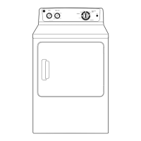
Visual guide identifying key components in an electric dryer.

Component Location - Gas Model

Gas Dryer Component Diagram

Visual guide identifying key components in a gas dryer.

Control Board Connector Identification

Control Board Connector Map

Identifies each connector and its associated function on the control board.

Component Removal: Control Panel

Control Panel Removal Steps

Detailed instructions for safely removing the control panel.

Component Removal: Panels

Top and Front Panel Removal

Instructions for removing the top and front panels to access internal parts.

Component Removal: Front Section

Door Switch, Drum Light, and Front Bulkhead

Steps to remove the door switch, LED drum light, and front bulkhead.

Drive Belt and Drum Service

Drive Belt Removal and Installation

Procedure for removing and reinstalling the dryer's drive belt.

Drum Roller Service

Drum Roller and Shaft Removal

Instructions for removing drum rollers and their support shafts.

Moisture Sensor System

Moisture Sensor Operation and Removal

Explains sensor function and how to remove sensor rods.

Belt Switch and Blower Wheel Service

Belt Switch and Blower Wheel Removal

Procedures to remove the belt switch and blower wheel.

Drum Motor Service

Drum Motor Removal Procedure

Step-by-step guide for removing the drum motor.

Motor and Heater Assembly Service

Long Vent Motor and Heater Removal

Instructions for removing the long vent motor and heater assembly.

Gas System Components

Burner Assembly and Gas Conversion

Details on the burner assembly and gas conversion kits.

Gas Valve Removal Steps

Procedure to remove the gas valve from the burner bracket.

Gas Valve Coil Service

Gas Valve Coil Removal Procedure

Instructions for removing the gas valve coils.

Ignition System Components

Ignitor and Flame Detector Removal

Steps for removing the ignitor and flame detector.

Ignition System Operation

Ignitor Circuit Operation Explained

Explanation of the glo-bar ignitor circuit and valve operation.

Back Panel Access

Back Panel Removal Procedure

Instructions for removing the back panel to access internal components.

Temperature Safety Controls

Inlet Safety Thermostat Function

Explains the inlet safety thermostat's role and operation.

Temperature Monitoring Components

Inlet Control Thermistor and High Limit Thermostat

Details inlet thermistor resistance and high limit thermostat function.

Airflow Temperature Sensors

Outlet Thermistor and Thermostat Service

Details outlet thermistor resistance and outlet thermostat function.

Control Board Assembly Service

Control Board Removal Guide

Step-by-step instructions to remove the main control board assembly.

Steam System Component Service

Misting Nozzle and Housing Removal

Procedure to remove the misting nozzle and its housing.

Water Valve Service Procedures

Water Valve Removal Steps

Instructions for removing the water valve for front or rear service.

Troubleshooting and Diagnostics

Service Test Mode Operation

How to enter, navigate, and utilize the service test mode.

Diagnostic Functions and Model Codes

Service Test Mode Functions List

Overview of available tests in service mode.

Dryer Model Code Reference

Table listing dryer models and their associated codes.

Error Code Reference Guide

Error Code Lookup and Descriptions

How to check error codes and their meanings.

Advanced Board Diagnostics

Dead Board Troubleshooting Steps

Procedures for diagnosing a non-responsive control board.

Component Electrical Testing

Moisture Sensor and Drum Light Tests

Testing procedures for moisture sensor rods and drum light.

Thermistor Resistance Testing

Inlet and Outlet Thermistor Resistance

How to measure resistance of inlet and outlet thermistors.

Heater Resistance Measurement

Electric Dryer Heater Resistance Check

Procedure to measure the resistance of the electric dryer heater.

Heater Voltage Measurement

Electric Dryer AC Voltage to Heater

How to test AC voltage supplied to the electric dryer heater.

Gas Valve Electrical Checks

Gas Valve Voltage and Amperage Testing

Procedures for checking gas valve voltage and amperage draw.

Motor Resistance Testing

Drum, Blower Motor Resistance Checks

How to measure resistance for various dryer motors.

Water Valve Electrical Testing

Water Valve Resistance and Voltage Test

How to perform resistance and voltage tests on the water valve.

Wiring Schematics Overview

Electric Model Schematic

General wiring diagram for electric dryer models.

Specialized Electric Schematics

Long Vent and Mist Electric Schematics

Wiring diagrams for specific electric dryer types.

Gas Model Wiring Schematic

Gas Dryer Schematic Overview

General wiring diagram for gas dryer models.

Specialized Gas Schematics

Long Vent and Mist Gas Schematics

Wiring diagrams for specific gas dryer types.

Electrical Voltage Checks

Electric Dryer AC Voltage to Board

Procedure to check AC voltage supply to the electric dryer board.

Gas Dryer AC Voltage Check

Gas Dryer AC Voltage to Board

Procedure to check AC voltage supply to the gas dryer board.

GE Dryer Warranty Information

Warranty Coverage and Exclusions

Details warranty periods, what is covered, and what is excluded.

Related product manuals