– 42 –
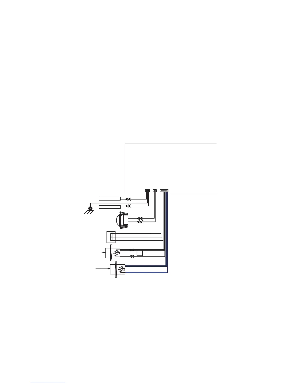
Inlet and Outlet Thermistors
Disconnect power from the dryer. Check from the J10 connector on the board. Set your meter to resistance
setting.
Inlet thermistor: Check resistance between the 2 WHITE wires.
Inlet control thermistor approximate resistance values:
• 59.4 - 65.7K at 69°F (20°C)
• 47.6 - 52.4K at 77°F (25°C)
• 38.4 - 42K at 86°F (30°C)
Outlet thermistor: Check resistance between the 2 BLUE wires.
Outlet control thermistor approximate resistance values:
• 118 - 122K at 69°F (20°C)
• 98 - 102K at 77°F (25°C)
• 78 - 82K at 86°F (30°C)
OUTLET
CONTROL
THERMISTOR
INLET CONTROL
THERMISTOR
N-20
N-20
Y-20
POWER BOARD
DSM
MODULE
O-20
GY-20
N-20
J10
1
1
J11
1
J25
1
R-20
B-20
UPPER ROD
LOWER ROD
S-20
P-20
GY-20
CHASSIS
BASE
3
Y-20
SEE NOTE 1
SEE NOTE 1
Note 1: This wire marked as Y (yellow) might be W (white) in some units.
(Continued Next Page)