– 34 –
Control Board Assembly
The control board assembly is mounted in a plastic
housing that is attached to the inside of the control
panel. It consists of 2 circuit boards connected by a
wire spine. The boards and the plastic housing are
replaced as an assembly.
Operation of the control board assembly can be
checked by using the service test mode. (See Service
Test Mode.)
Error codes that are specifi c to the control board
can initiate error codes F05 and E06. (See Service
Test Mode.)
To remove the control board assembly:
1. Remove the control panel. (See Control Panel and
follow steps 1 through 4.)
2. Pull the control knob straight out from the
control panel.
3. Place a protective surface on the top panel.
4. Lay the control panel face down on the
protected top panel.
5. Remove the 5 Phillips-head screws and the
control panel rear cover.
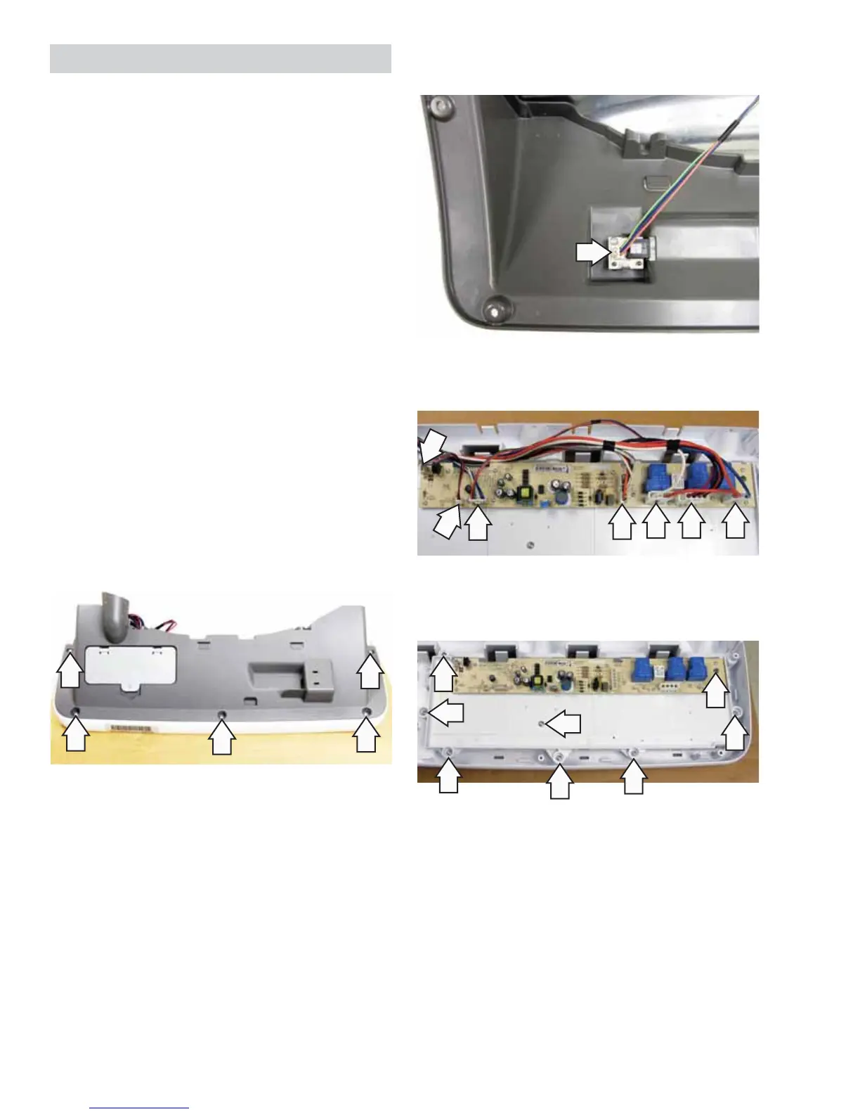
6. Disconnect the DMS wire harness from the
control panel rear cover.
7. Disconnect the wire harnesses from the control
panel.
8. Remove the 8 Phillips-head screws and the
control board frame from the control panel.