CHAPTER 2: INSTALLATION ELECTRICAL INSTALLATION
MM300 MOTOR MANAGEMENT SYSTEM – INSTRUCTION MANUAL 2–23
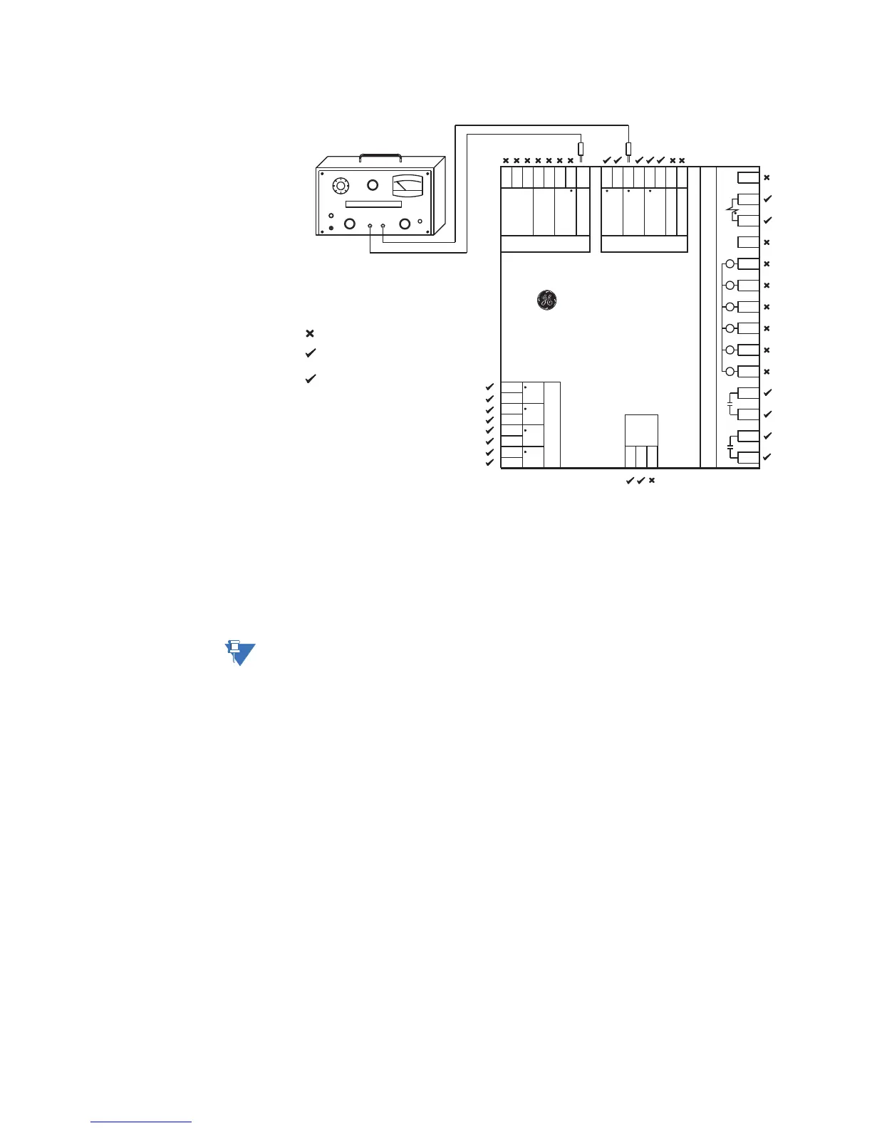
Figure 2-27: Testing for dielectric strength - with IO_E module
Filter networks and transient protection clamps are used between VT input and the surge
ground terminal. This is intended to filter out high voltage transients, radio frequency
interference (RFI), and electromagnetic interference (EMI). The filter capacitors and
transient suppressors may be damaged by continuous high voltage. Disconnect the surge
ground terminal (E8) during testing of VT inputs. The CT inputs, control power, and output
relays do not require any special precautions. Low voltage inputs (less than 30 volts), RTDs,
and RS485 communication ports are not to be tested for dielectric strength under any
circumstance (see above).
NOTE:
Substitute the slot position of the Input/Output module (E, F, G, or H) wherever the tilde
symbol “~” appears in the diagram above.
Do not HI-POT test
HI-POT test at 1.32 kV AC for 1 second, or
1.12 kV AC for 1 minute (per UL 508)
LINE FAULT
ON
POWER
FAULT
RESET
kV
VOLTAGE ADJUST
HV ON
DIELECTRIC STRENGTH TESTER
BLACK RED
Remove surge ground during test
*
~14
~13
~12
~11
~10
~9
~8
~7
~6
~5
~4
~3
~2
~1
AuxVT
CPU module
E8
E7
E6
E5
E4
E3
E2
E1
Surge Ground
D1
D2
D3
D4
D5
D6
D7
D8
CT Module
CT1
CT2
CT3
CT4
Power
supply
L
N
G
MM300
Motor Management System
GE Multilin
VT module (optional)
VT1
VT3
IO_E Module
RS485
Thermistor
VT2
Core
balance
Surge Ground
853738B3.CDR
+
–
C
+
–
R
ISG
COM
*
*
*
*
*



 To Next Page