CHAPTER 2: INSTALLATION STARTER TYPES
MM300 MOTOR MANAGEMENT SYSTEM – INSTRUCTION MANUAL 2–27
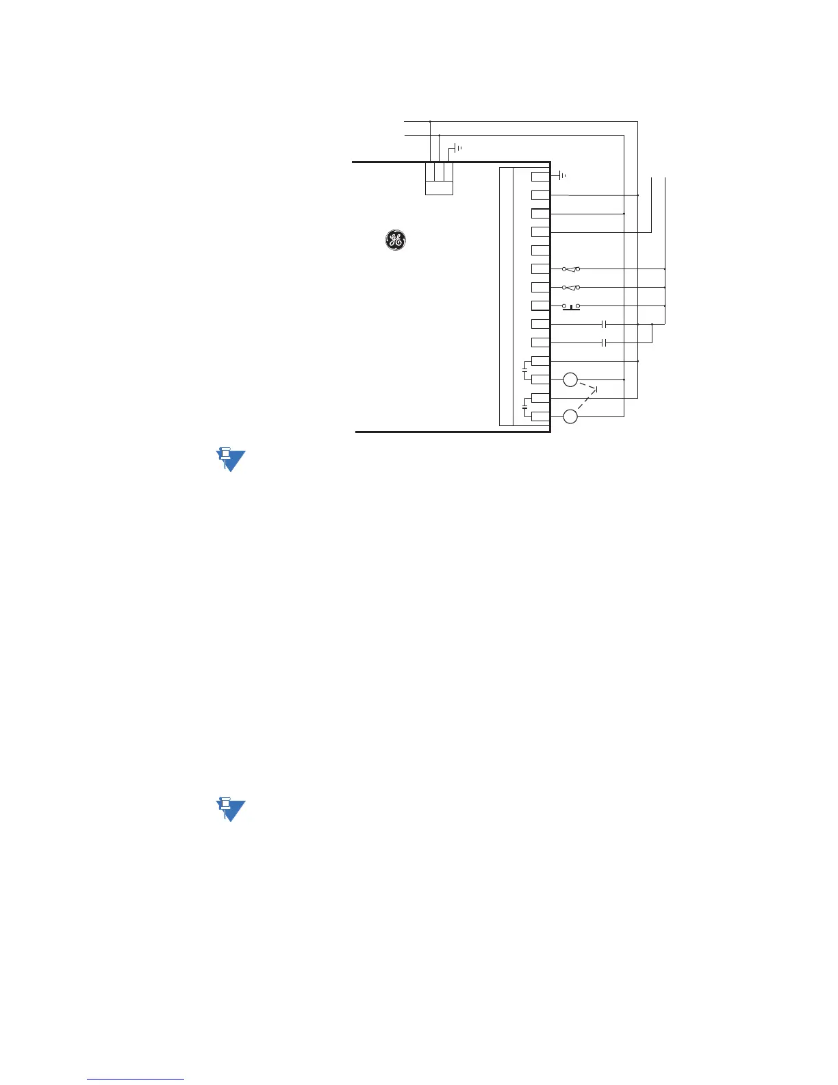
Figure 2-31: Full-voltage reversing starter control wiring - IO_E
NOTE:
The above drawing applies only to a high-voltage power supply. If a low-voltage (DC)
power supply is used, an appropriate DC voltage source must be used for this power
supply.
.
The full-voltage reversing starter type is a full voltage or across-the-line reversing starter.
When a start A (forward) control is received, the pre-contactor relay (if any) is picked up for
the set pre-contactor time. When the pre-contactor timer times out, relay1 picks up and
seals-in, picking up contactor F, which starts the motor in the forward direction. When a
start B (reverse) control is received, relay1drops out, and contactor F drops out. When the
contactor F Off status is received, the starter waits for the set transfer time to allow the
motor to slow or stop. When the transfer time timer times out, relay2 picks up and seals-in,
picking up contactor R, which starts the motor in the reverse direction. When a stop control
is received, relays 1 and 2 drop out, contactor F and R drop out, and the motor stops. The
starter logic is fully symmetrical between forward and reverse.
When a contact input has its function set to forward limit, and that contact closes, relay1
will drop out, stopping any forward rotation. When a contact input has its function set to
reverse limit, and that contact closes, relay2 will drop out, stopping any reverse rotation.
The pre-contactor is omitted on forced starts (for example, UVR Immediate, External Start).
Forced starts are not supervised by this starter transfer timer – any external starting circuit
must itself respect fast direction change restrictions.
NOTE:
Connect AUX VT to the Control Supply for correct operation of the UV Restart feature and
correct input readings.
.
R
Field Stop
Fwd Limit
F
F
Inter-
lock
R
Rev Limit
MM300
Low Voltage
Motor
Manager
C1
C2
C3
C4
C5
C6
C7
C8
C9
C10
C11
C12
C13
C14
Aux VT
IN 1 IN 2 IN 3 IN 4 IN 5 IN 6 Com
Relay 1Relay 2
LN
PSU
N
L
853705B3.cdr
I/O Module - Type E
Low Voltage
DC Supply to
I/O Type E
+
-
AC
Control Power
GE Multilin
G
 Loading...


