CHAPTER 2: INSTALLATION STARTER TYPES
MM300 MOTOR MANAGEMENT SYSTEM – INSTRUCTION MANUAL 2–37
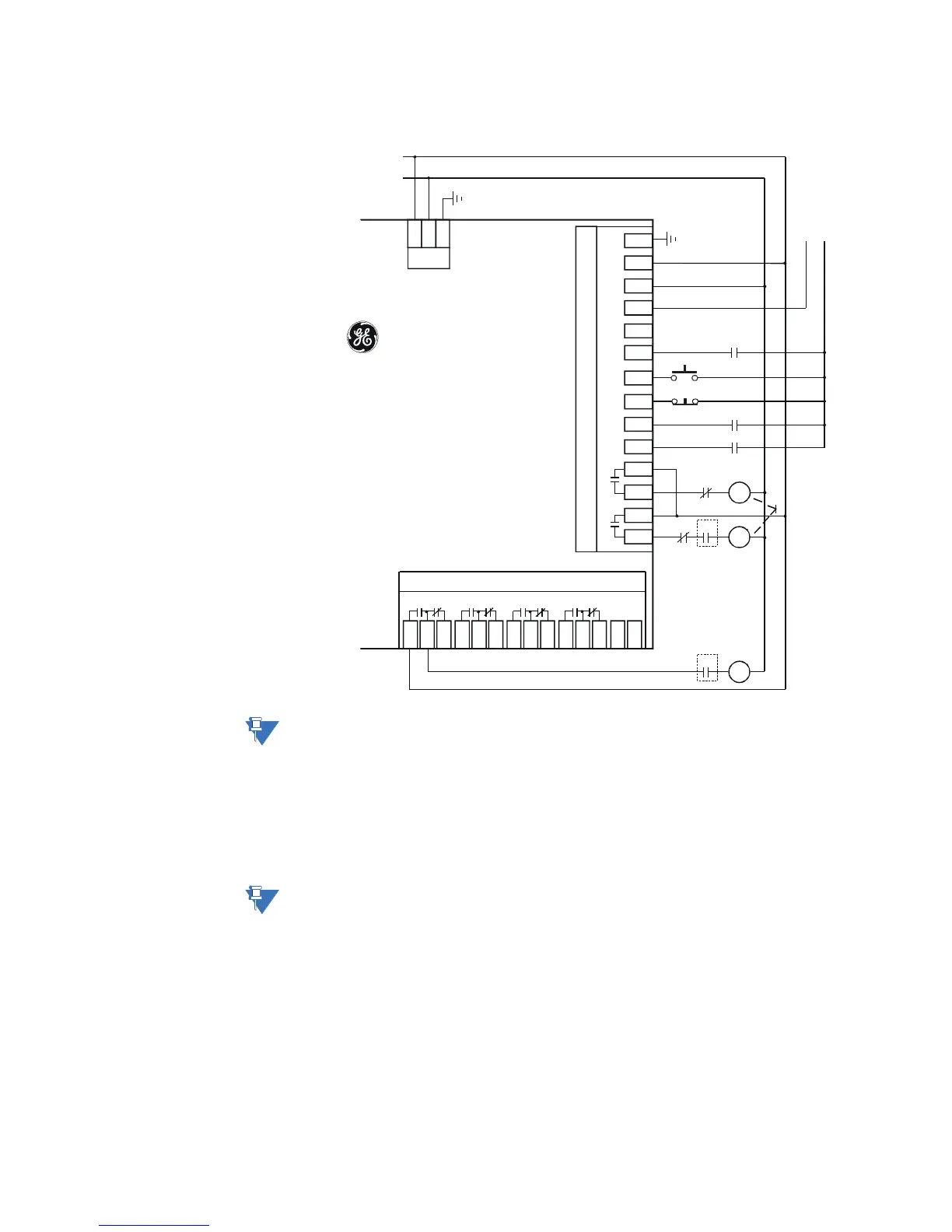
Figure 2-41: Autotransformer open transition starter typical control wiring - IO_E
(expansion module in slot "E")
NOTE:
The above drawing applies only to a high-voltage power supply. If a low-voltage (DC)
power supply is used, an appropriate DC voltage source must be used for this power
supply.
Autotransformer open transition starter is a reduced voltage starter. Three motor
contactors R, 1S and 2S each controlled by a separate MM300 output relay are used to
perform this function. There are two options of this starter: 1S-2S and 2S-1S. For more
details please refer to chapter Autotransformer open transition starter in section
Configuration setpoints / Motor setpoins section of the manual.
NOTE:
Connect AUX VT to the Control Supply for correct operation of the UV Restart feature and
correct input readings.
R
Field Stop
1S
1S
Int er lo ck
R
MM300
Low Voltage
Motor
Manager
C1
C2
C3
C4
C5
C6
C7
C8
I/O Module- Type E
C9
C10
C11
C12
C13
C14
IN1 IN 2 IN 3 IN4 IN5 IN6 Com
Rel ay
1
Re l ay 2
L
N
PSU
N
L
GEMultilin
G
1S
AUX V T
E1
E2
E3
Relay 1
E4
E5
E6
Relay 2
E7
E8
E9
Relay 3
E10
E11
E12
Relay 4
E13
E14
Not
Used
Expansion I/O Module - Type D
R 2S
Only for
2S-1S
sequence
2S
1S
Field Start
2S
Only for 1S-2S
sequence
AC Control
Power
Low Voltage DC
Supply to IO
Type E
-
+
Basic
853849A1.CDR



 To Next Page