EasyManua.ls Logo

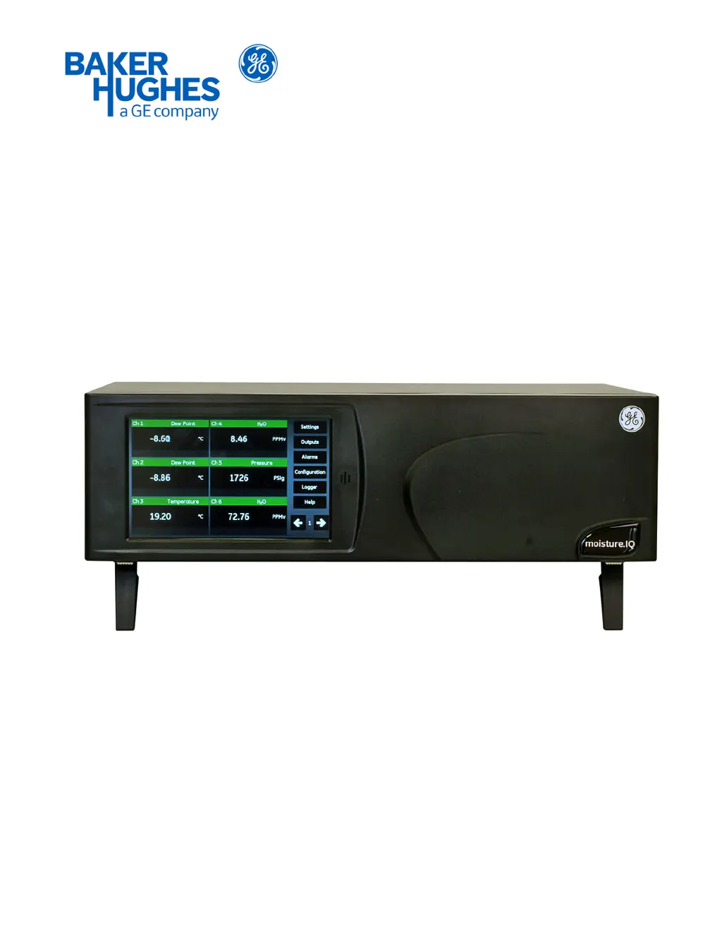
GE moisture.IQ - User Manual

GE moisture.IQ
182 pages
Print Icon
To Next Page IconTo Next Page
Loading...
Moisture and Oxygen
910-298 Rev. E
September 2017
bhge.com
moisture.IQ
Users Manual

Table of Contents

Other manuals for GE moisture.IQ

Questions and Answers

  • S
    sara03Sep 12, 2025
    Why does my GE moisture.IQ Analytical Instruments screen always read the driest moisture calibration value?
    • B
      bergchristinaSep 12, 2025
      If the GE Analytical Instruments screen always displays the driest programmed moisture calibration value, it could be due to an open circuit on the sensor. It could also be caused by non-conductive material trapped under the contact arm of the sensor, or an improper cable connection. You can clean the sensor and the sensor shield. Also, check the cable connections to both the probe and the moisture.IQ. If the low reading persists after cleaning, return the probe to the factory for evaluation.
  • A
    Andrea WalkerSep 10, 2025
    What does 'Under Range' mean on GE moisture.IQ Analytical Instruments?
    • J
      Jimmy CaldwellSep 10, 2025
      If the GE Analytical Instruments displays an 'Under Range' error, it means the input signal is below the calibrated range of the probe. If the measurement is not expected to be below scale, send the probe to GE for evaluation.
  • J
    Jeffrey BallSep 9, 2025
    Why does my GE moisture.IQ show a 'Cal Error'?
    • A
      Amy GarciaSep 9, 2025
      If the GE Analytical Instruments displays a 'Cal Error', it indicates that during Auto-Cal, an internal reference was found to be outside its acceptable range, meaning a signal error has occurred. To resolve this, ensure the analyzer is properly grounded and that the ground bolt is installed on the channel card. Remove the source of the signal error and attempt another Auto-Cal. Contact GE.
  • J
    Justin BairdAug 25, 2025
    What to do if GE Measuring Instruments screen always reads the driest value?
    • M
      michelemillerAug 26, 2025
      If your GE Measuring Instruments screen always reads the driest programmed moisture calibration value while displaying dew/frost point, it could be due to: * Open circuit on the sensor: Return the probe to the factory for evaluation. * Non-conductive material: Clean the sensor and the sensor shield as described in document 916-064, Basic Hygrometry Principles, and then reinstall the sensor. If the low reading persists, return the probe to the factory for evaluation. * Improper cable connection: Check the cable connections to both the probe and the moisture.IQ.
  • B
    Brad JacksonSep 6, 2025
    What to do if GE moisture.IQ Analytical Instruments screen always reads the wettest moisture calibration value?
    • M
      michele48Sep 7, 2025
      If the GE Analytical Instruments screen always displays the wettest programmed moisture calibration value, it could be due to several reasons. There might be liquid water present on the sensor surface or across electrical connections, indicating the probe is saturated. Another possibility is a shorted circuit on the sensor. Conductive particles contaminating the sensor could also cause this issue, as well as an improper cable connection. You can clean the sensor and sensor shield. Also, check the cable connections to both the probe and the moisture.IQ. If the high reading persists after cleaning, the probe is probably shorted and should be returned to the factory for evaluation.
  • J
    Jennifer TorresSep 5, 2025
    What does 'Cal Error' mean on GE Measuring Instruments?
    • M
      Melanie TateSep 5, 2025
      If the GE Measuring Instruments displays 'Cal Error', it means that during Auto-Cal, an internal reference was found to be outside its acceptable range. Make sure the analyzer is grounded properly, ensure the ground bolt is installed on the channel card, and remove any source of signal error before attempting another Auto-Cal.
  • S
    Sheena CurtisSep 4, 2025
    What does 'CHANNEL NOT AVAILABLE' mean on GE Measuring Instruments?
    • L
      Lori HardySep 4, 2025
      If the GE Measuring Instruments displays 'CHANNEL NOT AVAILABLE', it means that the module is not installed. Select a different channel.
  • R
    Raymond ParkSep 3, 2025
    What does 'Mode Fault!' mean on GE Measuring Instruments?
    • D
      Douglas MartinezSep 3, 2025
      If the GE Measuring Instruments displays '"Mode" Fault!', it indicates that the input signal from the probe exceeds the capacity of the analyzer electronics. If the measurement is not expected to be above scale, check the wiring for shorts. If no shorts are apparent, send the probe to BHGE for evaluation.
  • K
    keith08Sep 2, 2025
    What does 'NO PROBE' mean on GE Measuring Instruments?
    • S
      Sarah SchultzSep 2, 2025
      If the GE Measuring Instruments displays 'NO PROBE', it means that the unit has not been configured for the probe activated. Make sure the correct probe is activated and connect the required probe.
  • S
    sandra22Sep 1, 2025
    What does 'MIS NO LINK' mean on GE Measuring Instruments?
    • C
      Catherine RileySep 1, 2025
      If the GE Measuring Instruments displays 'MIS NO LINK', it means that communication with a Moisture Image Series Probe has failed, likely because the probe is disconnected or damaged. Check the Moisture Image Series Probe connections and replace the probe if necessary.

Summary

Preface

Product Registration

Register product for support, upgrades, and promotions.

Services

Offers training, product repairs, extended warranties, and service agreements.

Terms and Conditions

Information on sales terms, conditions, and warranty.

Typographical Conventions

Explains notes and important information formatting.

Safety Issues

Explains CAUTION and WARNING symbols and safety regulations.

Auxiliary Equipment Guidelines

Guidelines for operating auxiliary equipment and safety.

Environmental Compliance

Compliance with RoHS and WEEE directives.

Chapter 1. Installation

1.1 Introduction to Installation

Overview of installation into process systems and environmental factors.

1.2 Unpacking and Inspection

Instructions for unpacking, inspecting, and reporting damage.

1.3 Installing the moisture.IQ

Guidance on installing the unit, including safety warnings.

1.4 Installation Site Selection

Guidelines for selecting an optimal installation location.

1.5 Moisture Probe Considerations

Factors affecting probe performance and life, including handling and environment.

1.6 Sample System Guidelines

Guidelines for designing sample systems for moisture and oxygen measurement.

1.7 Mounting the Hygrometer System

Instructions for mounting the electronics unit, probes, and sample systems.

1.8 Installing the Probes

Steps for inserting moisture probes into sample cells and connecting oxygen cells.

1.9 Making Electrical Connections

General instructions for making electrical connections, including safety warnings.

1.10 Gas Flow for Oxygen Cell

Procedures and cautions for establishing gas flow through the Delta F Oxygen Cell.

1.11 Auxiliary Device Connection

How to power and connect auxiliary devices to the moisture.IQ.

1.12 Analog Output Connection

Connecting analog outputs to terminal blocks for recorders.

1.13 Alarm Connection

Details on connecting alarm relays, including pin designations.

Chapter 2. Operation

2.1 Powering Up the System

Sequence of screens observed when powering up the moisture.IQ.

2.2 Measurement Display Components

Description of items on the measurement display screen.

2.3 Help Button Usage

Accessing context-sensitive help information from any screen.

2.4 Data Element Editor

Configuring individual data measurements using the Data Element Editor.

2.5 Initial Setup Procedures

Steps for initial configuration of the moisture.IQ and attached probes.

2.6 System Restart

Procedure to restart (reboot) the moisture.IQ system.

2.7 System Shutdown

Procedure for safely shutting down the moisture.IQ system.

Chapter 3. Using the Settings Menu

3.1 Configuration Introduction

Overview of configuring the moisture.IQ for data collection.

3.2 Display Settings

Configuring the measurement screen, including items and brightness.

3.3 System Settings

Configuring global settings like date, time, and number format.

3.4 File Manager

Viewing and managing files stored in memory or on a USB drive.

3.5 Screen Alignment

Calibrating the LCD screen for optimal touch performance.

3.6 Screen Configuration

Adjusting touch screen sensitivity and orientation.

3.7 Notifications Setup

Specifying how often calibration reminders are displayed.

3.8 Fault Alarm Setup

Configuring the fault alarm relay response and listing fault sources.

3.9 Module Setup

Viewing installed sensor module information and firmware versions.

3.10 Service Menu Options

Accessing software updates, restarts, and shutdown options.

Chapter 4. Using the Outputs, Alarms and Logger Menus

4.1 Setting Up Outputs

Configuring analog outputs for channels, including mode, unit, and span.

4.1.1 Configuring an Output

Detailed steps for configuring analog output channels (A and B).

4.1.2 Testing Outputs

Steps to test output devices connected to the moisture.IQ.

4.1.3 Trimming Outputs

Compensating for load resistance variations in output signals.

4.1.4 Output Range Error Response

Configuring how outputs respond to under or over range errors.

4.2 Setting Up Alarms

Configuring optional alarms (A and B) for each channel.

4.2.1 Configuring an Alarm

Steps to set up alarm modes, units, and setpoints.

4.2.2 Testing Alarms

Testing alarm functionality by tripping and resetting them.

4.2.3 Alarm Range Error Response

Configuring alarm responses to under or over range errors.

4.3 Setting Up and Running Logs

Setting up and controlling data logging functions.

Chapter 5. Using the Configuration Menu

5.1 Configuring the Probes

Programming the moisture.IQ with probe measurement types and activating probes.

5.1.1 Probe Configuration Screen

Activating installed probes on each channel and selecting measurement modes.

5.1.2 Delta F Oxygen Sensor Probe Configuration

Selections available for Delta F Oxygen Sensor probes.

5.1.3 Calibrating Individual Channels

Steps for calibrating individual channels using dummy probes.

5.1.4 Probe Auto-Cal Schedule

Setting the frequency for the probe's automatic calibration function.

5.2 Calibrating Probes

Procedures for entering calibration data for probes.

5.2.1 Automatic Calibration Data Entry

Automatically entering calibration data from files.

5.2.2 Manual Calibration Data Entry

Manually entering calibration data points from sheets.

5.3 Tagging Inputs

Assigning custom tags to input parameters for display customization.

5.4 Entering User Information

Entering user-defined information like functions, tables, and constants.

5.4.1 Entering User Functions

Programming mathematical equations on each channel.

5.4.2 Entering User-Defined Tables

Creating up to six tables of non-linear data for user-defined functions.

5.4.3 Entering User Constants

Substituting user-defined constants for measurements and applying multipliers.

5.4.4 Entering Saturation Constants

Entering saturation values (Cs) for ppmw moisture calculations.

Chapter 7. Maintenance

7.1 Delta F Oxygen Cell Electrolyte

Checking and replenishing electrolyte in the oxygen cell due to gradual water loss.

7.1.1 Checking Electrolyte Level

Using the level indicator window to check the electrolyte level.

7.1.2 Replenishing Electrolyte

Instructions for adding distilled water to replenish the electrolyte.

7.2 Probe Replacement and Recalibration

Recommended frequency for sending probes for recalibration.

7.3 Delta F Oxygen Cell Calibration

Steps for calibrating the Delta F Oxygen Cell, including displaying content and checking calibration.

7.3.1 Displaying Oxygen Content

Determining the channel and configuring display for oxygen data.

7.3.2 Checking Oxygen Cell Calibration

Procedure to check oxygen cell calibration using calibration gas and a formula.

7.4 Delta F Oxygen Cell Background Gas Correction

Recalibrating for background gases other than nitrogen.

7.4.1 Correcting for Different Background Gases

Deriving correction factors for gases other than nitrogen.

Chapter 8. Troubleshooting

8.1 Screen Messages

Listing screen messages, possible causes, system responses, and actions.

8.2 Common Problems

Troubleshooting common issues with moisture sensor accuracy and response.

Chapter 9. Specifications

9.1 Electronics Specifications

Intrinsic safety, inputs, auxiliary inputs, and analog/alarm outputs.

9.2 Moisture Measurement Specifications

Type, calibration ranges, accuracy, repeatability, and operating pressure.

9.3 Temperature Measurement Specifications

Type, calibration ranges, and accuracy for temperature measurement.

9.4 Pressure Measurement Specifications

Type, available ranges, accuracy, and pressure rating.

9.5 Oxygen Measurement Specifications

Type, available ranges, accuracy, and pressure rating.

9.6 General Specifications

Display, temperature, warm-up time, and data logging details.

9.7 Output Specifications

Analog/digital outputs, alarm relays, and output updating details.

9.8 Input Specifications

Input capability, resolution, probe/sensor types, and intrinsic safety.

9.9 Probe Specifications

Specifications for Moisture Image Series and M Series probes.

Appendix A. Menu Maps

A.1 Settings Menu Map

Visual representation of the Settings menu structure.

A.2 Outputs, Alarms, Logger Menu Map

Visual representation of the Outputs, Alarms, and Logger menu structure.

A.3 Configuration > Probe & User Menu Maps

Visual representation of Configuration menu for Probes and User settings.

A.4 Configuration > Comms Menu Map

Visual representation of Configuration menu for Communications settings.

Appendix B. Wiring Diagrams

B.1 Terminal Blocks Wiring

Wiring details for terminal blocks and rear view of the unit.

B.2 Rear View Channel Configurations

Diagrams showing different channel configurations on the rear view.

B.3 Power Wiring Diagrams

Wiring diagrams for power connections to the unit.

B.4 RS-485 Wiring Diagram

RS-485 wiring diagram for communication.

Appendix C. Updating the moisture.IQ Firmware

C.1 Updating Chassis Firmware

Steps to update the main chassis firmware using a USB flash drive.

C.2 Updating Module Firmware

Loading and plugging in the USB flash drive for module firmware update.

Appendix D. Modbus Register Map

Modbus Register Map Table

Table detailing Modbus registers for error, analog outputs, and channels.

GE moisture.IQ Specifications

General IconGeneral
BrandGE
Modelmoisture.IQ
CategoryAnalytical Instruments
LanguageEnglish

Related product manuals