CHAPTER 5: SETPOINTS
489 GENERATOR MANAGEMENT RELAY – INSTRUCTION MANUAL 5–79
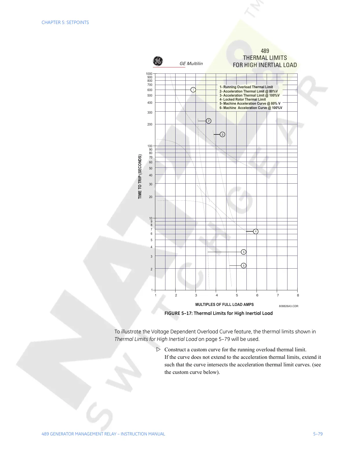
FIGURE 5–17: Thermal Limits for High Inertial Load
To illustrate the Voltage Dependent Overload Curve feature, the thermal limits shown in
Thermal Limits for High Inertial Load on page 5–79 will be used.
Z Construct a custom curve for the running overload thermal limit.
If the curve does not extend to the acceleration thermal limits, extend it
such that the curve intersects the acceleration thermal limit curves. (see
the custom curve below).
489
THERMAL LIMITS
FOR HIGH INERTIAL LOAD
808826A3.CDR
1
1 23 45 6 78
2
3
4
5
6
7
8
9
10
20
30
40
50
60
70
80
90
100
TIME TO TRIP (SECONDS)
MULTIPLES OF FULL LOAD AMPS
200
300
400
500
600
700
800
900
1000
1
2
3
4
6
5
1- Running Overload Thermal Limit
2- Acceleration Thermal Limit @ 80%V
3- Acceleration Thermal Limit @ 100%V
4- Locked Rotor Thermal Limit
5- Machine Acceleration Curve @ 80% V
6- Machine Acceleration Curve @ 100%V
GE Multilin
Courtesy of NationalSwitchgear.com