CHAPTER 5: SETPOINTS
489 GENERATOR MANAGEMENT RELAY – INSTRUCTION MANUAL 5–85
significant increase in rotor heating. This extra heating is not accounted for in the thermal
limit curves supplied by the generator manufacturer as these curves assume positive
sequence currents only that come from a perfectly balanced supply and generator design.
The 489 measures the ratio of negative to positive sequence current. The thermal model
may be biased to reflect the additional heating that is caused by negative sequence
current when the machine is running. This biasing is done by creating an equivalent
heating current rather than simply using average current (I
per_unit
). This equivalent current
is calculated using the equation shown below.
(EQ 5.32)
where: I
eq
= equivalent motor heating current in per unit (based on FLA)
I
2
= negative-sequence current in per unit (based on FLA)
I
1
= positive-sequence current in per unit (based on FLA)
k = constant relating negative-sequence rotor resistance to positive-sequence
rotor resistance, not to be confused with the k indicating generator negative-
sequence capability for an inverse time curve.
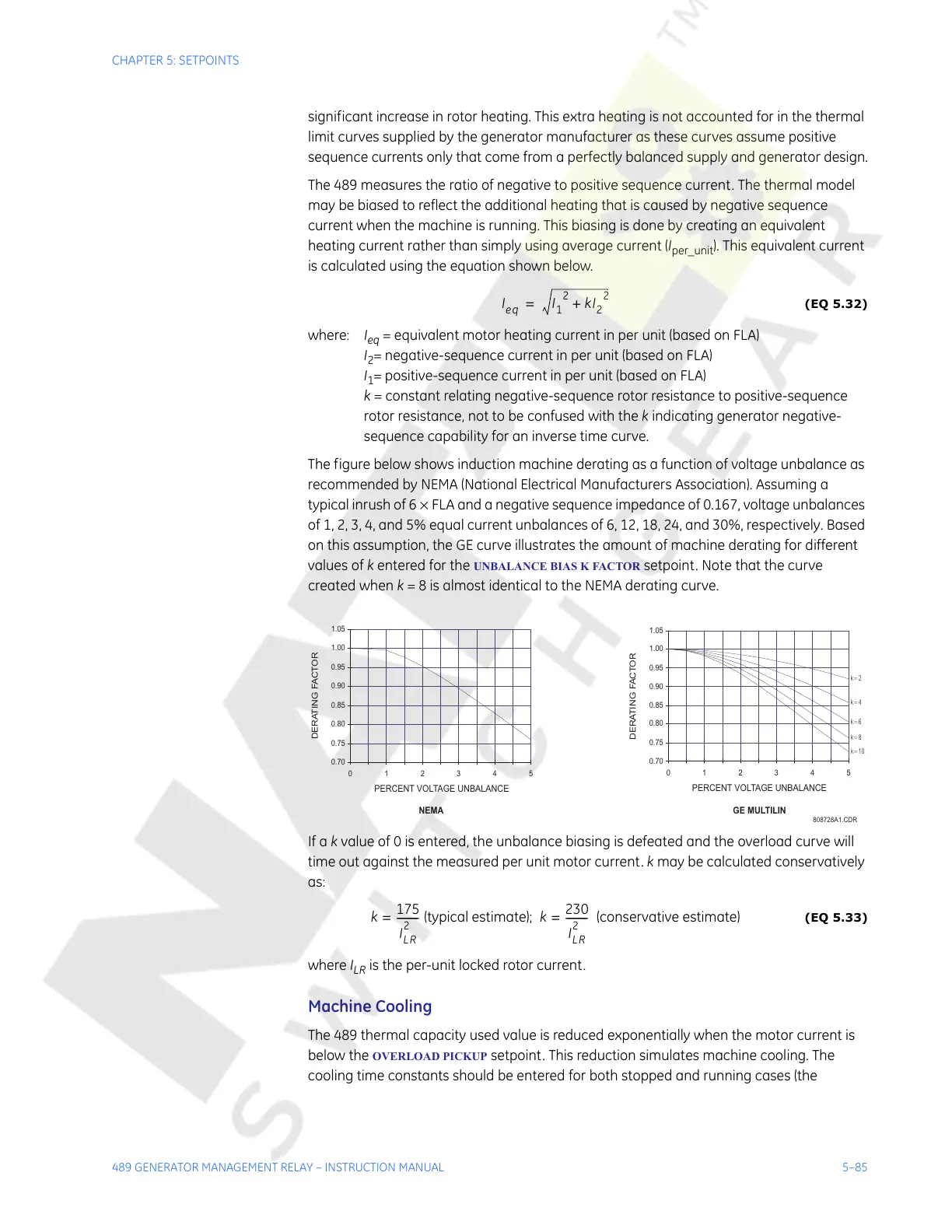
The figure below shows induction machine derating as a function of voltage unbalance as
recommended by NEMA (National Electrical Manufacturers Association). Assuming a
typical inrush of 6 × FLA and a negative sequence impedance of 0.167, voltage unbalances
of 1, 2, 3, 4, and 5% equal current unbalances of 6, 12, 18, 24, and 30%, respectively. Based
on this assumption, the GE curve illustrates the amount of machine derating for different
values of k entered for the
UNBALANCE BIAS K FACTOR setpoint. Note that the curve
created when k = 8 is almost identical to the NEMA derating curve.
If a k value of 0 is entered, the unbalance biasing is defeated and the overload curve will
time out against the measured per unit motor current. k may be calculated conservatively
as:
(EQ 5.33)
where I
LR
is the per-unit locked rotor current.
Machine Cooling
The 489 thermal capacity used value is reduced exponentially when the motor current is
below the
OVERLOAD PICKUP setpoint. This reduction simulates machine cooling. The
cooling time constants should be entered for both stopped and running cases (the
808728A1.CDR
0.70
0.75
0.80
0.85
0.90
0.95
1.00
1.05
012345
PERCENT VOLTAGE UNBALANCE
DERATING FACTOR
k=2
k=4
k=6
k=8
k=10
0.70
0.75
0.80
0.85
0.90
0.95
1.00
1.05
012345
PERCENT VOLTAGE UNBALANCE
DERATING FACT OR
NEMA GE MULTILIN
k
175
I
LR
2
---------= (typical estimate); k
230
I
LR
2
---------= (conservative estimate)
Courtesy of NationalSwitchgear.com