S4 Elements745
Transformer Management Relay
Setpoints
http://www.GEindustrial.com/multilin
5–42
GE Multilin
b) Percent Differential
PATH: SETPOINTS !" S4 ELEMENTS !" DIFFERENTIAL ! PERCENT DIFFERENTIAL
This section contains the settings to configure the percent differential element. The
main purpose of the percent-slope characteristic of the differential element is to
prevent maloperation because of unbalances between CTs during external faults.
These unbalances arise as a result of the following factors:
• CT ratio mismatch (not a factor, since the 745 automatically corrects for this
mismatch)
• Onload tap changers which result in dynamically changing CT mismatch
• CT accuracy errors
• CT saturation
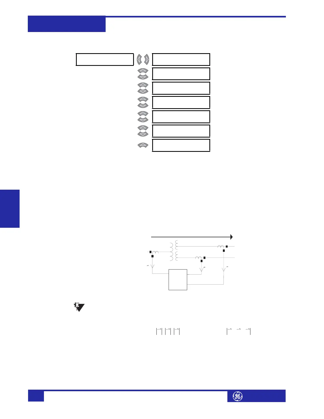
The basic operating principle of the percent differential element can be described by
the following diagram and its associated equations:
FIGURE 5–6: Percent Differential Operating Principle
Restraint current calculations have been changed from average to
maximum to provide better security during external faults.
The basic percent differential operating principle for three-winding transformers is
illustrated by the following equations:
(EQ 5.4)
The basic percent differential operating principle for two-winding transformers is
illustrated by the following equations:
! PERCENT [!]
DIFFERENTIAL
PERCENT DIFFERENTIAL
FUNCTION: Enabled
Range: Enabled, Disabled
MESSAGE
PERCENT DIFFERENTIAL
TARGET: Latched
Range: Self-Reset, Latched, None
MESSAGE
PERCENT DIFFERENTIAL
PICKUP: 0.30 x CT
Range: 0.05 to 1.00 x CT in steps of
0.01
MESSAGE
PERCENT DIFFERENTIAL
SLOPE 1: 25%
Range: 15 to 100% in steps of 1
MESSAGE
PERCENT DIFFERENTIAL
KNEEPOINT: 2.0 x CT
Range: 1.0 to 20.0 x CT in steps of 0.1
MESSAGE
PERCENT DIFFERENTIAL
SLOPE 2: 100%
Range: 50 to 100% in steps of 1
MESSAGE
PERCENT DIFFERENTIAL
BLOCK: Disabled
Range: Logc Inpt 1 to 16, Virt Inpt 1 to
16, Output Rly 2 to 8, SelfTest
Rly, Vir Outpt 1 to 5, Disabled
Percent
Diff
Element
CT1
CT2
CT3
V1
V2
V3
I
1
I
2
I
3
NOTE
I
r
I
restraint
max I
1
I
2
I
3
,,()== ; I
d
I
differential
I
1
I
2
I
3
++==
%slope
I
d
I
r
-----
100%×=