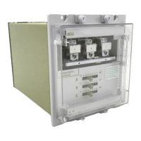
S4 Elements
745
Transformer Management Relay
Setpoints
http://www.GEindustrial.com/multilin
5–73
GE Multilin
• MINIMUM OPERATING VOLTAGE: Enter the minimum value of voltage (in
terms of nominal VT secondary voltage) required to allow the Volts-per-Hertz 1
element to operate.
• VOLTS-PER-HERTZ 1 PICKUP: Enter the volts-per-hertz value (in V/Hz)
above which the Volts-per-Hertz 1 element will pickup and start the delay timer.
• VOLTS-PER-HERTZ 1 SHAPE: Select the curve shape to be used for the Volts-
per-Hertz 1 element. The inverse volts-per-hertz curve shapes are shown
below.
• VOLTS-PER-HERTZ 1 DELAY: Enter the time that the volts-per-hertz value
must remain above the pickup level before the element operates.
• VOLTS-PER-HERTZ 1 RESET: Enter the time that the volts-per-hertz value
must remain below the pickup level before the element resets.
The curve for the Inverse Curve 1 shape is derived from the formula:
(EQ 5.12)
where T = operate time (seconds)
D = delay setpoint (seconds)
V = fundamental RMS value of voltage (V)
F = frequency of voltage signal (Hz)
Pickup = volts-per-hertz pickup setpoint (V/Hz)
FIGURE 5–33: Volts Per Hertz Curve 1
The curve for the inverse curve 2 shape is derived from the formula:
(EQ 5.13)
where T = operate time (seconds)
D = delay setpoint (seconds)
V = fundamental RMS value of voltage (V)
F = frequency of voltage signal (Hz)
Pickup = volts-per-hertz pickup setpoint (V/Hz)
T
D
VF⁄
Pickup
-------------------
2
1–
------------------------------------- -= when
V
F
--- -
Pickup>
0.01
0.1
1
10
100
1000
1.00 1.20 1.40 1.60 1.80 2.00
Multiples of Volts/Hertz Pickup
Time
Delay
Setting
ò
10
3
1
0.3
0.1
Time to Trip (seconds)
T
D
VF⁄
Pickup
------------------- 1–
-----------------------------= when
V
F
--- -
Pickup>
 Loading...


