S4 Elements745
Transformer Management Relay
Setpoints
http://www.GEindustrial.com/multilin
5–76
GE Multilin
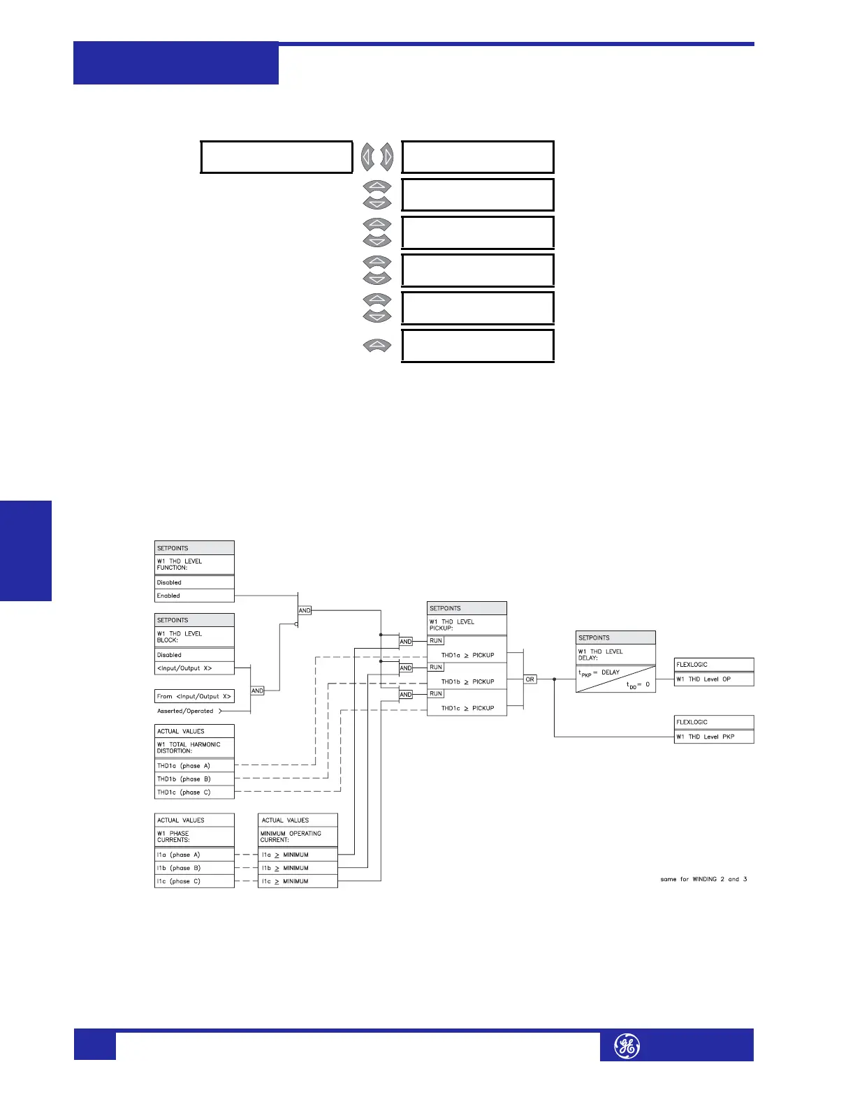
b) THD Level
PATH: SETPOINTS !" S4 ELEMENTS !" HARMONICS ! W1(3) THD LEVEL
• MINIMUM OPERATING CURRENT: Enter the minimum value of current (in
units of relay nominal current) required to allow the THD level element to
operate.
• W1(3) THD PICKUP LEVEL: Enter the total harmonic distortion (in %ƒ
0
)
above which the Winding 1(3) Total Harmonic Distortion element level will
pickup and start the delay timer.
• W1(3) THD LEVEL DELAY: Enter the time that the total harmonic distortion
must remain above the pickup level before the element operates.
FIGURE 5–37: THD Level Scheme Logic
! W1 THD LEVEL [!] W1 THD LEVEL
FUNCTION: Disabled
Range: Enabled, Disabled
MESSAGE
W1 THD LEVEL
TARGET: Self-Reset
Range: Self-Reset, Latched, None
MESSAGE
MINIMUM OPERATING
CURRENT: 0.10 x CT
Range: 0.03 to 1.00 x CT in steps of
0.01
MESSAGE
W1 THD LEVEL
PICKUP: 50.0% f0
Range: 0.1 to 50.0% f
0
in steps of 0.1
MESSAGE
W1 THD LEVEL
DELAY: 10 s
Range: 0 to 60000 s in steps of 1
MESSAGE
W1 THD LEVEL
BLOCK: Disabled
Range: Logc Inpt 1 to 16, Virt Inpt 1 to
16, Output Rly 2 to 8, SelfTest
Rly, Vir Outpt 1 to 5, Disabled