Protection Schemes745
Transformer Management Relay
Commissioning
http://www.GEindustrial.com/multilin
7–14
GE Multilin
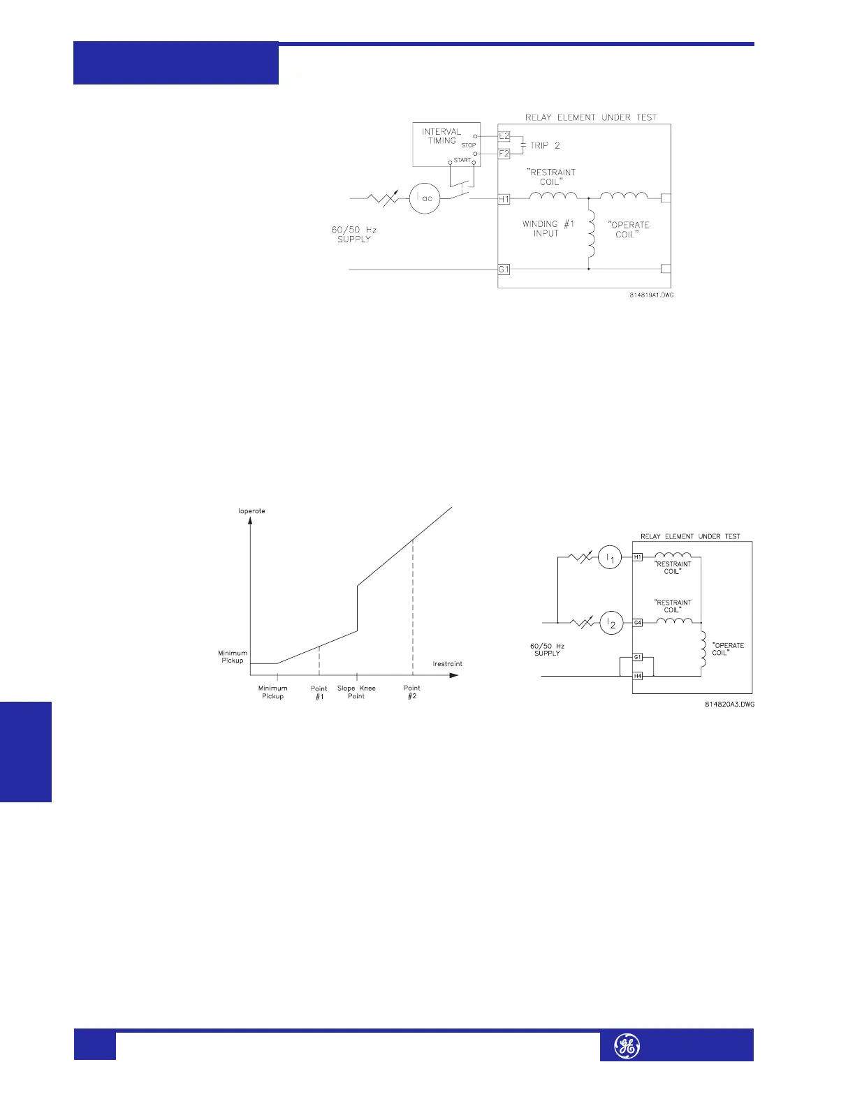
FIGURE 7–5: Timer Test Circuit
g) Slope Measurements
The auto configuration processes the currents to correct for phase shifts, CT
mismatch, and zero sequence component removal. As such, it more complex to
measure the slope from an external single phase injection. Therefore, the use of
displayed actual values is recommended.
The differential and restraint currents are displayed the
A2 METERING ! CURRENT !"
DIFFERENTIAL ! PHASE A DIFFERENTIAL CURRENT and A2 METERING !" CURRENT !"
RESTRAINT ! PHASE A RESTRAINT CURRENT actual values:
1. To measure the slope, connect current signals to the relay as shown in the fig-
ure below:
FIGURE 7–6: Current Signal Connections
2. If I
1
= 1.5 × CT and I
2
= 0, the element is operated as all the current appears as
a differential current.
3. The slope is calculated from the values of I
differential
and I
restraint
as follows:
. (EQ 7.11)
4. Slowly increase I
2
. As I
2
is increased, the element will reset when the
differential current drops below the minimum pickup.
5. As I
2
continues to increase, the element operates again when both the initial
slope and the minimum pickup conditions are satisfied. Calculate the initial
slope 1 value at this point.
6. As I
2
increases further, the element may reset again, depending on the setting
of the slope kneepoint. This is caused by the current values moving into the
slope 2 region.
7. Continue increasing I
2
until the element operates again. Compute the slope 2
value at this point.
%slope
I
differential
I
restraint
-------------------------------
100%×=