B-82 G60 Generator Protection System GE Multilin
B.4 MEMORY MAPPING APPENDIX B
B
[62] MISCELLANEOUS EVENTS (see F146 for range)
[64 to 127] ELEMENT STATES
F400
UR_UINT16: CT/VT BANK SELECTION
F491
ENUMERATION: ANALOG INPUT MODE
0 = Default Value, 1 = Last Known
F500
UR_UINT16: PACKED BITFIELD
First register indicates input/output state with bits 0 (MSB) to 15
(LSB) corresponding to input/output state 1 to 16. The second reg-
ister indicates input/output state with bits 0 to 15 corresponding to
input/output state 17 to 32 (if required) The third register indicates
input/output state with bits 0 to 15 corresponding to input/output
state 33 to 48 (if required). The fourth register indicates input/out-
put state with bits 0 to 15 corresponding to input/output state 49 to
64 (if required).
The number of registers required is determined by the specific
data item. A bit value of 0 = Off and 1 = On.
F501
UR_UINT16: LED STATUS
Low byte of register indicates LED status with bit 0 representing
the top LED and bit 7 the bottom LED. A bit value of 1 indicates
the LED is on, 0 indicates the LED is off.
F502
BITFIELD: ELEMENT OPERATE STATES
Each bit contains the operate state for an element. See the F124
format code for a list of element IDs. The operate bit for element ID
X is bit [X mod 16] in register [X/16].
F504
BITFIELD: 3-PHASE ELEMENT STATE
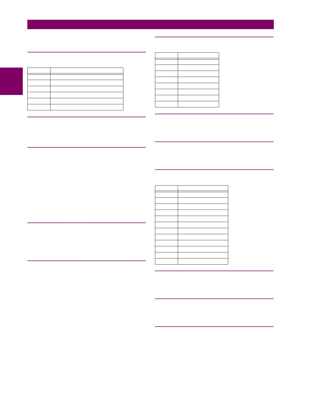
F505
BITFIELD: CONTACT OUTPUT STATE
0 = Contact State, 1 = Voltage Detected, 2 = Current Detected
F507
BITFIELD: COUNTER ELEMENT STATE
0 = Count Greater Than, 1 = Count Equal To, 2 = Count Less Than
F508
BITFIELD: DISTANCE ELEMENT STATE
F509
BITFIELD: SIMPLE ELEMENT STATE
0 = Operate
F511
BITFIELD: 3-PHASE SIMPLE ELEMENT STATE
0 = Operate, 1 = Operate A, 2 = Operate B, 3 = Operate C
F513
ENUMERATION: POWER SWING MODE
0 = Two Step, 1 = Three Step
bitmask bank selection
0 Card 1 Contact 1 to 4
1 Card 1 Contact 5 to 8
2 Card 2 Contact 1 to 4
3 Card 2 Contact 5 to 8
4 Card 3 Contact 1 to 4
5 Card 3 Contact 5 to 8
bitmask element state
0Pickup
1 Operate
2 Pickup Phase A
3 Pickup Phase B
4 Pickup Phase C
5 Operate Phase A
6 Operate Phase B
7 Operate Phase C
bitmask distance element state
0Pickup
1 Operate
2Pickup AB
3Pickup BC
4 Pickup CA
5 Operate AB
6 Operate BC
7 Operate CA
8Timed
9 Operate IAB
10 Operate IBC
11 Operate ICA

 Loading...


