3.3.2 Test Set-Up for RF Shielded Room
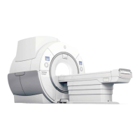
The RF shielded room is set up for shielding effectiveness testing with a normal configuration
consisting of:
1.
Magnet installed including all floor mounting bolts (including dock anchor bolt)
2.
RF shielded door(s)
3. Waveguide penetrations, HVAC, vents, medical gas lines, etc.
4. AC power supplied through low-pass filters
5.
Patient view window, skylights, windows, hatches, etc.
6. Frames and blank penetration panels installed, dimensionally equivalent to the GE panel
and the same mounting hardware to be used with the GE penetration panel.
NOTE: A GE Field Engineer is responsible for disconnecting cryocooler lines. For safety
reasons, the enclosure will be electrically grounded during the shielding effectiveness
test. Any variances from the normal configuration will be noted in the RF shield test
report
3.3.3 Shielding Effectiveness (SE)
The final shielding effectiveness performance of the RF shielded room is determined based on
the lowest measurement of all test point locations.
3.3.4 Reference Level and Dynamic Range
1. The reference level is the value of signal measured by the receiver equipment with the
receiving antenna located at a prescribed distance from the transmit antenna and located
outside of the shielded enclosure
2.
The dynamic range (DR) is the range of amplitudes over which the receive system operates
linearly. The dynamic range must be at least 6 dB greater than the SE to be measured. For
SE measurement, the dynamic range is the difference of the reference level to the noise
floor
3.3.5 Test Equipment
1. Test equipment must be selected to provide measuring capabilities as described in this test
method
2.
Any piece of equipment, whose operation directly affects the numerical value of the
Shielding Effectiveness (SE), must be in calibration before any critical measurements are
begun. Dates of calibration traceable to a national standard must be provided in the test
report (see Section 3.3.9 for test report requirements) and must be within the calibration
cycle of the equipment. The calibration cycle of equipment must be no greater than 2 years.
3.
All equipment must be verified for proper operation between and after each series of tests
by repeating the reference readings at the specified frequency.
4.
Required equipment for transmit chain of measurement system:
a. Frequency Synthesizer or Signal Generator.
SIGNA Voyager Pre-Installation
Direction 5680008–1EN, Revision 2
Chapter 7 Appendix 159

 Loading...