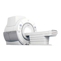
Illustration 3-20: Magnet Cryogenic Vent Location
8.8 Combined Vent
A site can combine cryogen venting from two GEHC MR systems.
NOTE:
The customer chooses this option with the risk that a magnet quench may quench the
second magnet.
The waveguides of each system can connect via 45 degree elbow connectors to a 12 in. (305)
pipe as shown in the illustration below. The pipe must be sealed at the bottom, and a plate must
be fully welded to the inside of the pipe to correctly direct all cryogens out of the magnet room.
The plate and pipe used for the combined vent must be the same as the waveguide material.
1.
The total pressure drop of the cryogenic venting system for each magnet (from the flanged
vent adaptor to the vent exit including the vent exit) must be less than 17 psi (117.2 kPa).
2. The pressure drop in the shared section of the vent must not exceed 4 psig
3. The combined vent pipe diameter selected to maintain the pressure drop will require the
combined pipe section diameter meet the back pressure and 35 psi internal pressure forces
4. The two magnet vents require a plate separating the entering pipes to prevent one magnet
quench from imposing a back pressure to the other magnet
5.
The separation plate must be able to withstand the quench up to 35 psi internal pressure
caused by the impinging gas flow. Inspection/replacement of combined pipe section should
the separation plate distort post quench.
6. The venting system must have a structural support along any pipe section elbow and at the
joining of the two (2) magnet vents to the combined vent.
SIGNA Voyager Pre-Installation
Direction 5680008–1EN, Revision 2
Chapter 3 Magnet Room 93

 Loading...