6. Control Functions and Parameter Settings
6-28
Block-C parameters (Extended function constants) list
ApplicationNo. Parameter Unit Default Min. Max. Function
ST V/f VEC PM
C24 – Speed detection error monitor
0 Overspeed protection
level
% 105.0 100.0 200.0 The overspeed protection operation
level is set.
1 Control mode change-
over during speed
detection error
1. 1. 3. Select control at speed detection error
= 1 : Speed detection error not
monitored
= 2 : Speed detection error
monitored (Do not change to
sensor-less vector control)
= 3 : Speed detection error
monitored (Switch to sensor-
less vector control)
2
Speed detection error
level
% 10.0 1.0 100.0
3 Speed detection error
recovery level
% 5.0 1.0 100.0
The conditions for judging the speed
detection error are set.
Set as C24-2
≥
C24-3.
C25 – High-efficiency operation
0 Voltage reduction time sec 1.0 0.1. 30.0
Set the time for the output voltage to
drop from the V/f setting value to 0V.
1 Voltage lower limit
setting value
% 100. 10. 100. When selecting a high-efficiency
operation function, set 10 to 99.
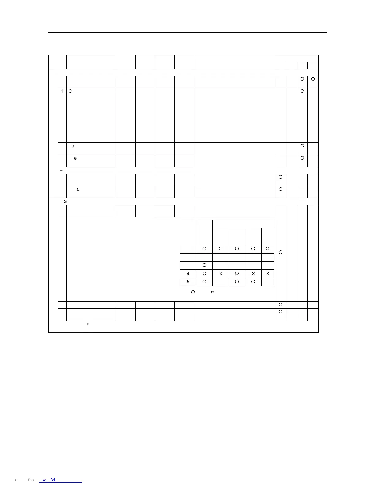
C26 – Standard serial transmission setting
0
Parameter change
lock
1. 1. 5.
The parameters are shown in below
table
: Changeable X: Lock
1 Station Number 1. 0. 32. Set the station number
2 Response timer sec 0.00 0.00 2.00 Set the minimum time for returning an
answer after receiving the command
Refer to instruction manual (PCST-3298)
Block B, C
Sett-
ing
value
Block
A
Basic Ex-
tend
S/W H/W
1
2XXXXX
3
XXXX
4
X
XX
5
X
X