6. Control Functions and Parameter Settings
6-29
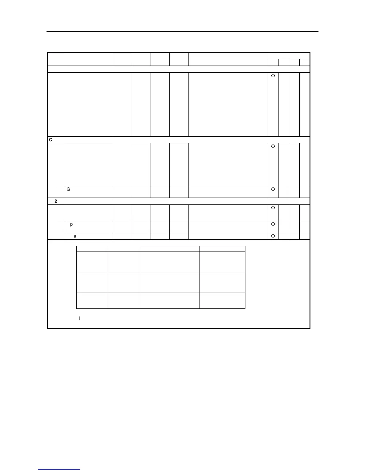
Block-C parameters (H/W extended functions) list
ApplicationNo. Parameter Unit Default Min. Max. Function
ST V/f VEC PM
C30 – Control mode selection
0 Control mode
selection
— 1. 4. The control mode is set.
= 1 : V/f control (constant torque:
overload characteristics
150% for one minute.)
= 2 : V/f control (variable torque:
overload characteristics
120% for one minute.)
= 3 : Speed sensor-less vector
control
= 4 : Speed vector control with
sensor
= 5 : PM Motor control
C31 – Main circuit option selection
0 DBR option selection 1. 1. 4. = 1 : Both Dynamic braking
and motor loss braking
disabled
= 2 : Dynamic Braking enabled
= 3 : Motor loss braking enabled
= 4 : Both Dynamic braking
and motor loss braking
enabled
1
Ground fault detection
function
1. 1. 2. = 1 : Enabled = 2 : Disabled
C32 – PC Parallel interface
0 Input mode (strobe) 1. 1. 3. = 1 : 16-bit
= 2 : 8-bit
= 3 : 16-bit sample
1 Input mode (input
logic)
1. 1. 2. = 1 : 1 at ON input status
= 2 : 0 at OFF input status
2 Data format 1. 0. 10. Set according to the following table
Parallel communications need option U2KV23PIO. Refer to instruction manual PCST-3303 for details
Setting data Format Setting resolution Setting range
0 16-bits binary 0,01Hz/LSB (0.1rpm/LSB) 0 to 440.00Hz
1 16-bits binary 0,01Hz/LSB (1rpm/LSB) 440.0 Hz
2 16-bits binary 0,01%/LSB 100.00%
3 16-bits binary 0,1%/LSB 100.0%
4 16-bits BCD 0,01Hz/LSB (0.1rpm/LSB) 99.99Hz
5 16-bits BCD 0,01Hz/LSB (1rpm/LSB) 100.0Hz
6 16-bits BCD 0,01%/LSB 99.99%
7 16-bits BCD 0,1%/LSB 100.0%
8 8-bits BCD 1/255% 100.0%
9 12-bits BCD 1/4095% 100.0%
10 16-bits BCD 1/65535% 100.0%