3.5 Functional description
3.5.1 Pneumatic Actuator
The compressed air which enters above the piston causes a downwards
movement of the piston and the disk of the butterfly valve opens or closes,
depending on the definition of the resting position. When the air supply is shut off,
the valve closes automatically as a result of the spring force.
The stroke of the piston is converted into a rotary movement of the shaft. The
travel of the piston is limited, so that the shaft performs a 90° rotation per stroke.
This rotation exactly corresponds to the rotational angle required to open or close
the disk of the butterfly valve.
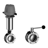
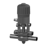
3.5.2 Actuator A.1
Fig.10
The switching state is detected and indicated by the control top (B).
The visual position indication (O) can be recognized by the red marking.
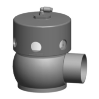
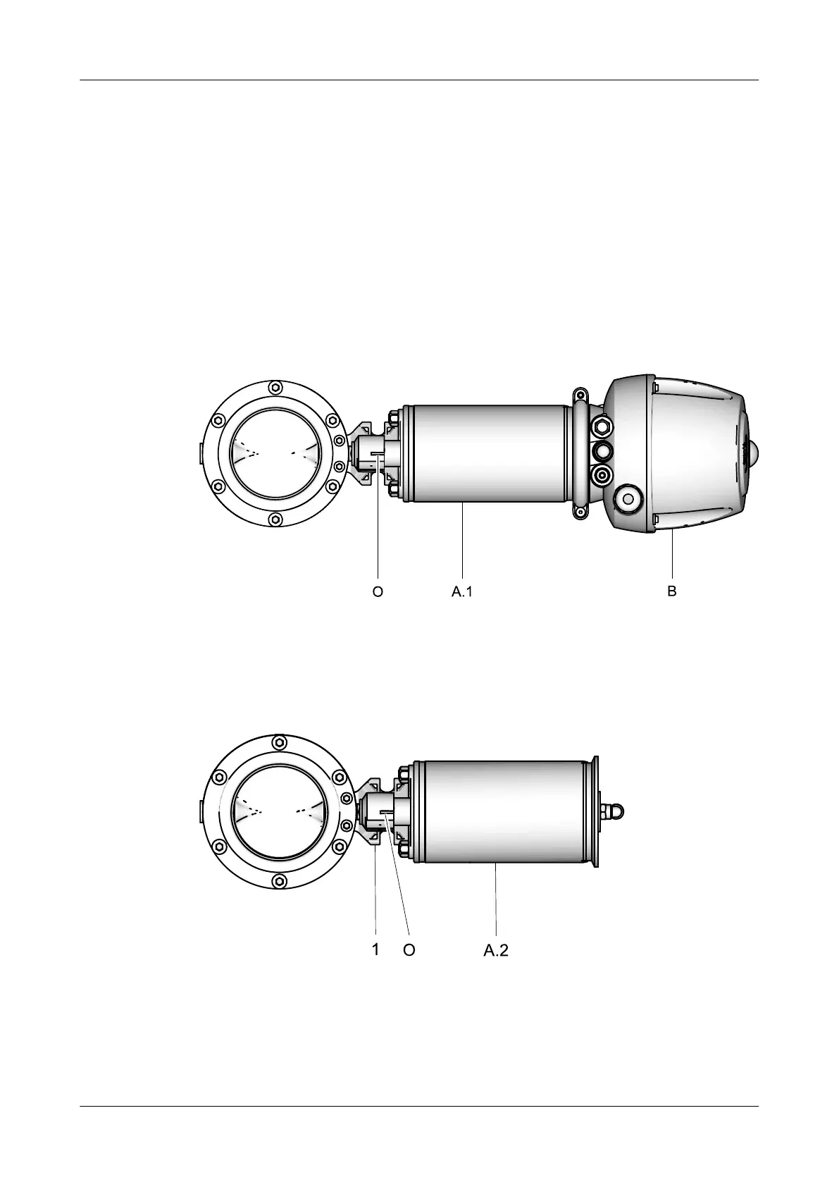
3.5.3 Actuator A.2
Fig.11
Feedback of switching states can be provided by proximity switches in the
mounting bracket (1). The resting position can be reported by proximity switches
that can be attached to the mounting bracket as required.
Description
Functional description
430BAL009990EN_2
30.01.2018 19
 Loading...