6.6.1 Air Requirement
The air requirement for the switching operations depends on the actuator type.
Actuator type Actuator Ø (mm)
Air requirement (dm
3
n
/
stroke) dm
3
n
at 1.01325
bar at 0°C in
accordance with DIN
1343
BFV-7 83 88.9 0.325
BFV-7 109 114.3 0.530
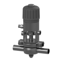
6.6.2 Establishing Hose Connections
To ensure reliable operation, the compressed air hoses must be cut exactly
square.
Tools required:
•
A hose cutter
Carry out the following steps:
1.
Shut off the compressed air supply.
2.
Use the hose cutter to cut the pneumatic hoses square.
3.
Push the air hose into the air connector on the control top.
4.
Re-open the compressed air supply.
®
Establish a hose connection.
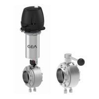
6.6.3 Actuator with T.VIS Control Top
Carry out the following steps:
1.
Push the air hose into the air connector on the control top.
2.
Re-open the compressed air supply.
®
Done
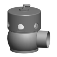
6.6.4 Actuator without Control Top
Carry out the following steps:
1.
Remove the screw plugs from the cylinder.
2.
Screw in the air connector G 1/8“
3.
Push the air hose into the air connector.
4.
Re-open the compressed air supply.
®
Done
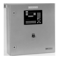
6.7 Electrical connections
Assembly and installation
Electrical connections
430BAL009990EN_2
32 30.01.2018
 Loading...