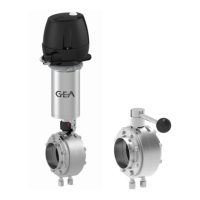
3.
Weld the plain flanges in position in the pipe system, ensuring that the
connection is free of stress and distortion. Use the TIG welding with pulse
method.
4.
Screw the butterfly valve body to the plain flanges.
! Installation outer flange type VV: Arrange additional holes so that bracket (K)
can be dismantled in assembled condition.
5.
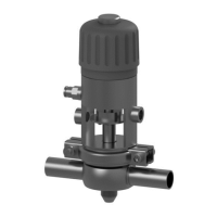
Fit the complete actuator (A).
®
Done
Hint!
Fit exhaust air/supply air flow control devices for all compressed-air
operated design variants. This way you prevent pipe hammers.
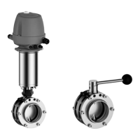
6.5 Butterfly valve with screw connection (G, K, C)
Carry out the following steps:
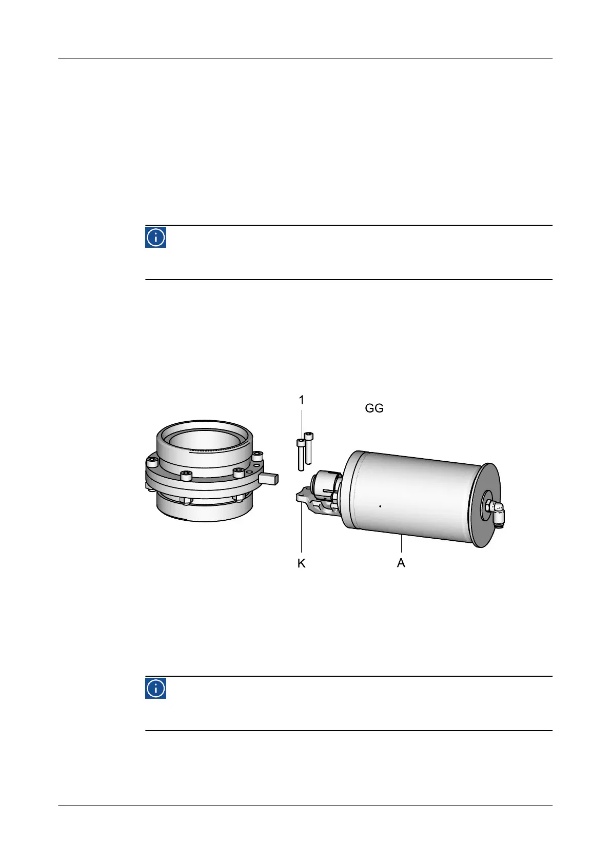
1.
Remove the complete actuator (A).
To do so, unscrew the screws (1) from the bracket (K) and the butterfly valve
body.
Fig.17
2.
Open the pipe connection at the connection fittings.
3.
Fit the butterfly valve body to the connection fittings.
4.
Fit the complete actuator (A).
®
Done
Hint!
Fit exhaust air/supply air flow control devices for all compressed-air
operated design variants. This way you prevent pipe hammers.
6.6 Pneumatic connections
Assembly and installation
Butterfly valve with screw connection (G, K, C)
430BAL009990EN_2
30.01.2018 31
 Loading...