The visual position indication (O) can be recognized by the red marking.
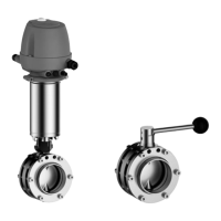
3.5.4 Manual Actuator Type H
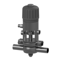
Fig.12
To open or close the valve, release the hand lever (1) by gently pulling it out of
the locking device and turning it by 90°. When the lever is released, it locks into
place in the holes provided. The limit positions of the butterfly valve can be
detected by proximity switches.
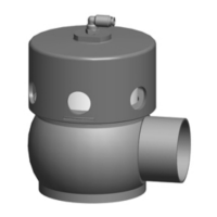
3.5.5 Butterfly Valve Body without Actuator
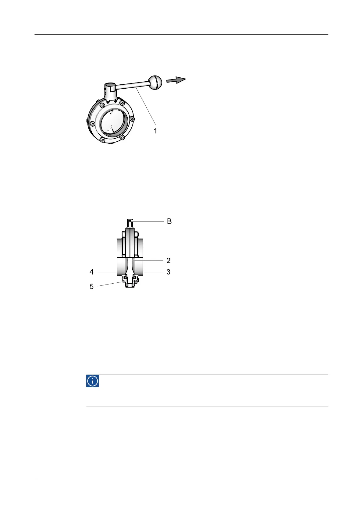
Fig.13
The valve disk (2) is supported between two flanges screwed together (3, 4) and
a separate plain bearing (5).
Depending on the actuator position, the valve disk is opened to different angles
and activated in the pipe opened. If the blade of the disk is parallel to the centre
axis of the pipe, the butterfly valve is located in the fully opened position and
guarantees maximum flow. When in the closed position, the blade of the valve
disk blocks the flow of the butterfly valve.
Hint!
The hole (B) in the square end and the markings on the lower shaft are
used as position indicators for the valve disk.
Description
430BAL009990EN_2
20 30.01.2018
 Loading...