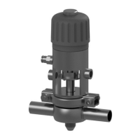
EasyManuals Logo

GEA T-smart 7 User Manual

GEA T-smart 7
96 pages
To Next Page IconTo Next Page
To Previous Page IconTo Previous Page
Page #45 background imageLoading...
Page #45 background image
Fig.22
Carry out the following steps:
1.
Undo the screw connections (1).
2.
Lift off the actuator (A).
®
Done
Hint!
The red position indication marker (2) is aligned with the hole (B) in
the disk so that it indicates the position of the disk in the valve.
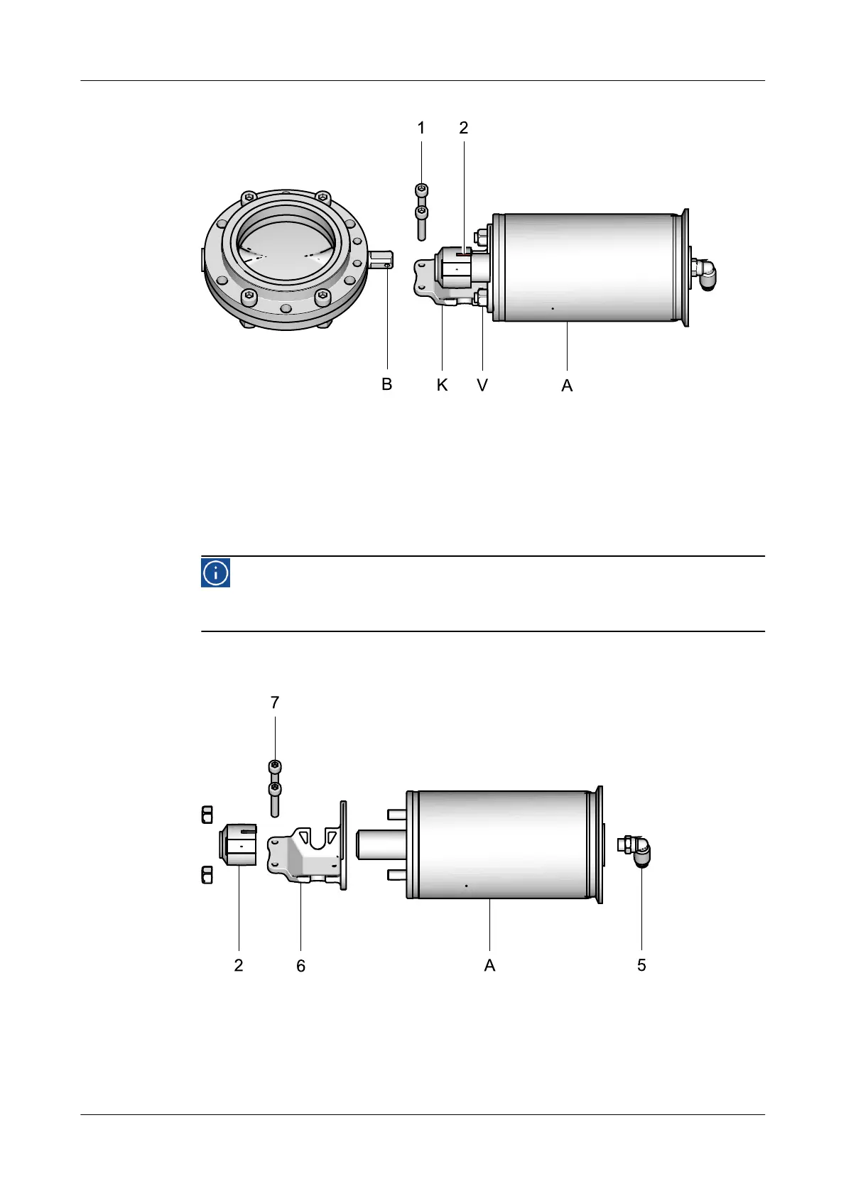
10.5.6 Dismantling the Actuator Parts
Fig.23
Carry out the following steps:
1.
Undo the screw connections (7).
Maintenance
Disassembling the Valve
430BAL009990EN_2
30.01.2018 45

Table of Contents

Questions and Answers:

Question and Answer IconNeed help?

Do you have a question about the GEA T-smart 7 and is the answer not in the manual?

GEA T-smart 7 Specifications

General IconGeneral
BrandGEA
ModelT-smart 7
CategoryControl Unit
LanguageEnglish

Related product manuals