•
When the actuator is mounted, the disk must be in the correct position: for
resting position closed: disk closed for resting position open: Disk at 90°
position.
•
Installation outer flange type VV: Arrange additional holes so that bracket can
be dismantled in assembled condition.
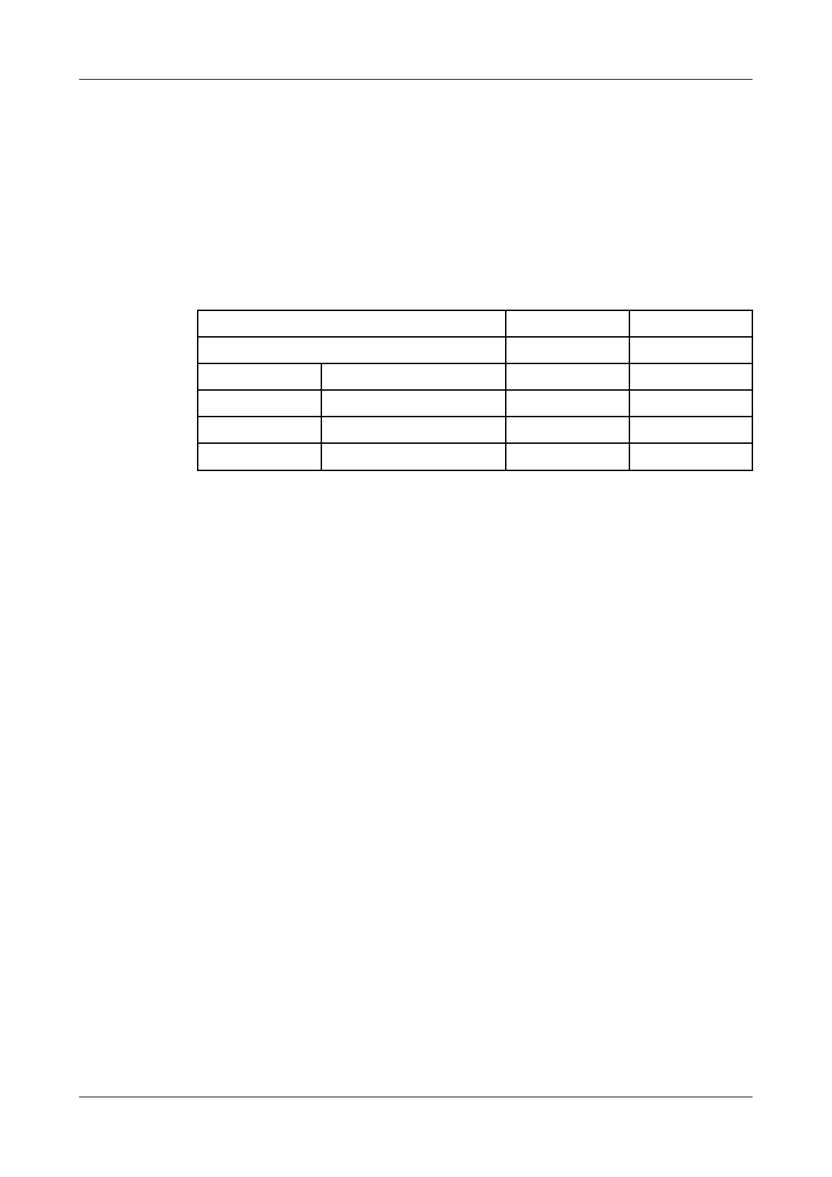
10.7.2 Torques for the Clamps and Clamp Connections
Tighten the clamp connection and semi-rings on the valve to the torques
specified in the table.
Torques [Nm] [lbft]
Clamps on the control top 1 0.7
Bolts M6 9 6.6
Bolts M8 22 16.2
Bolts M10 45 33
Bolts M12 78 57.5
Maintenance
430BAL009990EN_2
52 30.01.2018
 Loading...