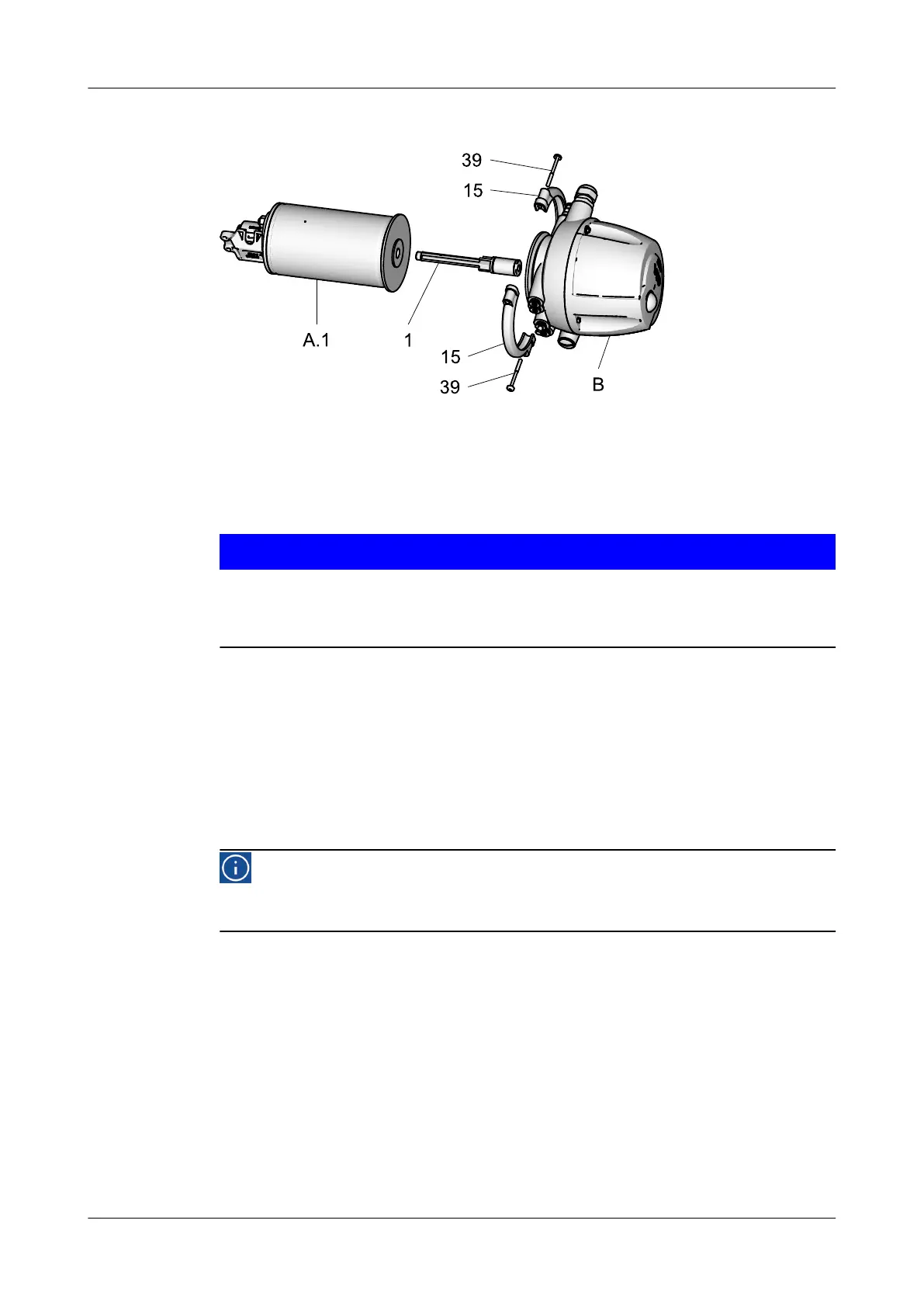
10.5.1 Removing the T.VIS M-15 Control Top
Fig.18
Prerequisite:
•
The pneumatic and electrical connections on the plant side can remain on the
control top.
Notice!
The permanent magnet on the switch bar is fragile.
Damage to the permanent magnet.
► Protect the permanent magnet against impact stress.
Carry out the following steps:
1.
Undo the screws (39).
2.
Remove the clamps (15).
3.
Withdraw the control top (B) via the switch bar (1) from the actuator (A.1).
4.
Unscrew the switch bar (1).
®
Done
Hint!
Assemble the valve in reverse order. Also refer to the instruction
manual for the T.VIS M-15.
Maintenance
Disassembling the Valve
430BAL009990EN_2
42 30.01.2018
 Loading...