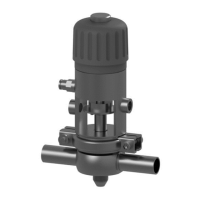
1.
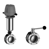
Remove the complete actuator (A).
To do so, unscrew the screws (1) from the bracket (K) and the butterfly valve
body.
Fig.15
2.
Cut the pipe open at the point of installation.
3.
Weld the butterfly valve body in position in the pipe system, ensuring that the
connection is free of stress and distortion. Use the TIG welding with pulse
method.
4.
Remove the welding beads.
5.
Fit the complete actuator (A).
®
Done
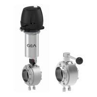
6.4 Butterfly Valve with Intermediate Flange Design
Carry out the following steps:
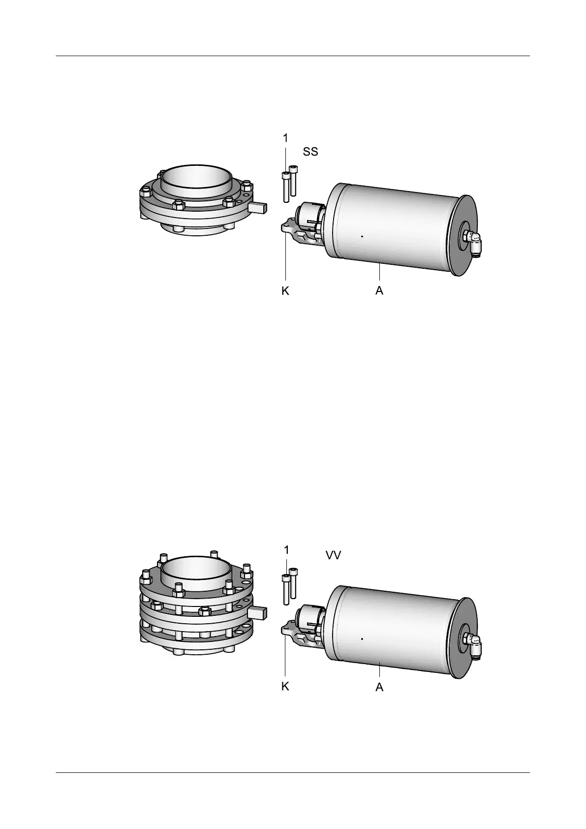
1.
1. Remove the complete actuator (A).
To do so, unscrew the screws (1) from the bracket (K) and the butterfly valve
body.
Fig.16
2.
Detach the plain flanges from the butterfly valve body.
Assembly and installation
Butterfly Valve with Intermediate Flange Design
430BAL009990EN_2
30 30.01.2018
 Loading...