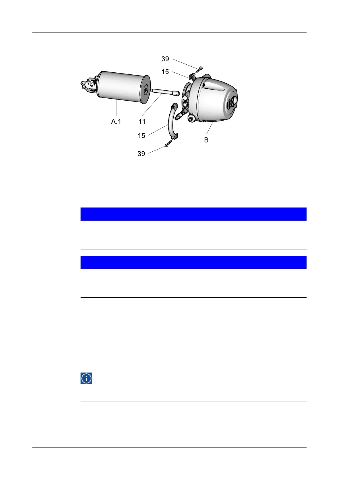
10.5.2 Removing control top type T.VIS P-15 and A-15
Fig.19
Prerequisite:
•
The pneumatic and electrical connections on the plant side can remain on the
control top.
Notice!
The permanent magnet on the switch bar is fragile.
Damage to the permanent magnet.
► Protect the permanent magnet against impact stress.
Notice!
The sensor is a sensitive component.
Damage of the sensor and failure of the valve.
► Always handle the sensor with care!
Carry out the following steps:
1.
Undo the screws (39).
2.
Remove the clamps (15).
3.
Withdraw the control top (B) via the switch bar (11) from the actuator (A.1).
4.
Unscrew the switch bar (11).
®
Done
Hint!
Assembly in reverse order (also refer to the instruction manual for the
T.VIS P-15 / A-15).
Maintenance
Disassembling the Valve
430BAL009990EN_2
30.01.2018 43
 Loading...