170
CONTROL FUNCTIONS 650 1250 1350
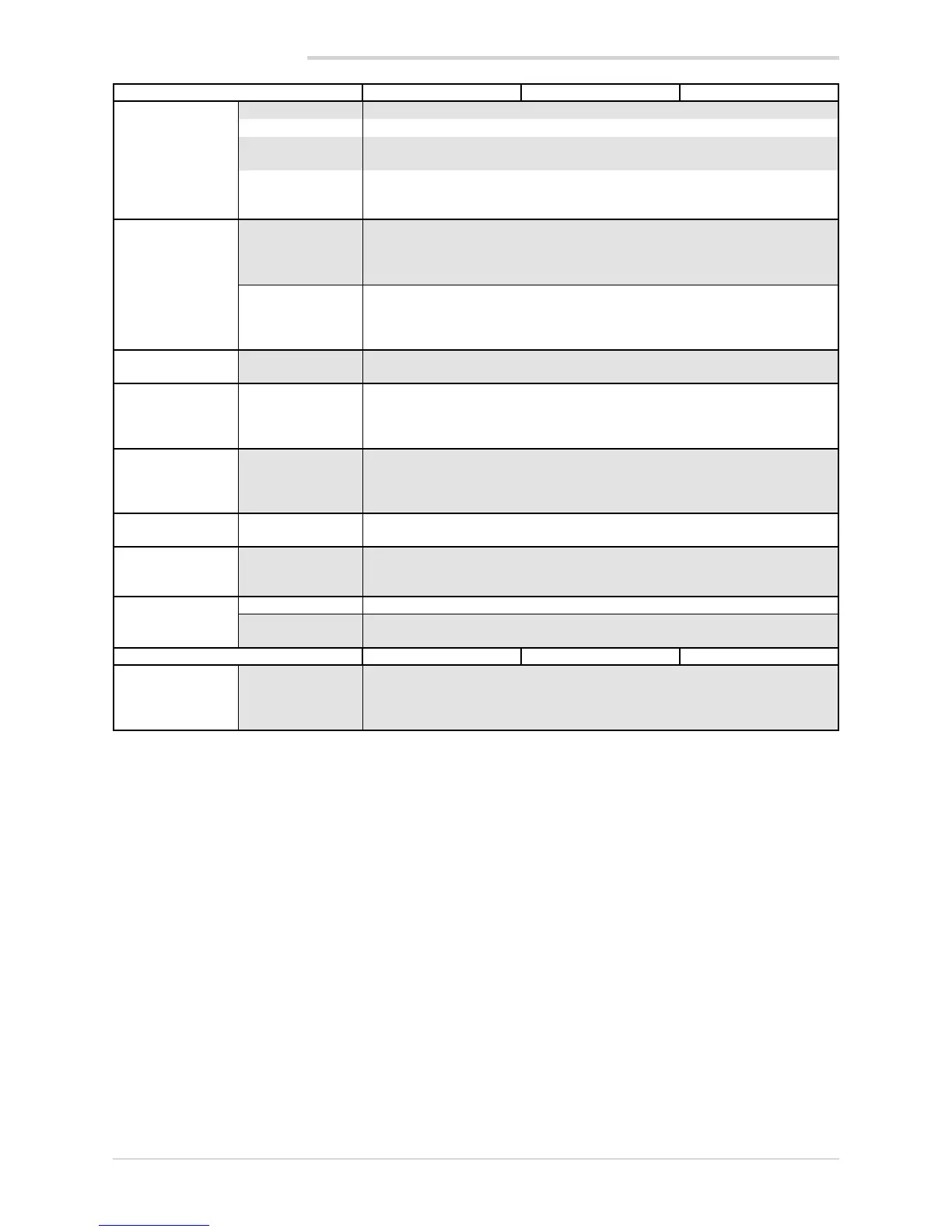
CONTROL
Type Single loop
Control PID, ON/OFF, single action heat or cool, double action heat/cool
Control output Continuous or ON/OFF
Cycle time: constant or optimized (BF)
Control output for
motorized
valves
OPEN/CLOSE for floating motorized valve on Relay, Solid-state,
Triac outputs
SETPOINT
PROGRAMMER
Number of
programs
Max 4
Start / Stop / Reset / Skip via digital inputs and/or outputs from
logic operations
Output state: Run /Hold / Ready / End
Number of steps Max 12, each with own setpoint, ramp time and hold time
Times settable in HH:MM or MM:SS
Max 4 consents, configurable for ramp and for hold
Max 4 events, configurable in ramp and in hold
MULTIPLE
SETPOINTS
Number of setpoin-
ts
Max 4, selectable from digital input
Each setpoint change is subject to set ramp, different for up and down ramp
LOGIC
1
OPERATIONS
Function blocks Max 16, with 4 input variables per block.
The result can act on the state of the controller, of the programmer on alarms
and outputs.
Each function contains an incorporated timer block timer.
TIMER
FUNCTION
Modes START / STOP
STABILIZATION (timer is on when PV enters a band set around setpoint; at end
of count you can activate an output, shut down SW or change SP1/SP2)
FIRING (timed activation of control after power on)
ENERGY COUN-
TER
Calculation done on nominal line voltage and nominal load power or on rms
current measured on load via CT
DIAGNOSTIC
Short circuit or open circuit (LBA alarm)
Interrupted or partially interrupted load (HB alarm)
Short circuit of control output (SSR alarm)
RETENTIVE
MEMORY
Type EEPROM
Max. number of
writes
1.000.000
SERIAL INTERFACE 650 1250 1350
Type: RS485
Baudrate: 1200, 2400, 4800, 9600, 19.200, 38.400, 57.600,115.200 bit/s
Protocoll: MODBUS RTU
Isolated from main input
1) Programming is done with the GF_eXpress configuration program.
9. TECHNICAL DATA