ADP200 Application PID-IMM User Manual Pag. 11 of 80
Digital Input (T1):
M9 = EN HW - Enable (not programmable)
M8 = DI1 – Start
M4 = DI5 – Fault Reset
Analog Input (T2):
M72 = AIS 0V : Pressure sensor 0V
M71 = AIS 24V : Pressure sensor 24V
M70 = AIS In+ : Analog Input pressure sensor +
M99 (T2) = PE :Shield Pressure sensor cable
M43 = AI1+ : Pressure Reference +
M42 = AI1- : Pressure Reference -
M41 = AI2+ : Flow Reference +
M40 = AI2- : Flow Reference -
M81 = M01+ : Motor protection input +
M80 = M01 - : Motor protection Input –
M99 (T3) = PE :Shield Motor protection cable
Digital Output (T3):
M27 = DO1 : Drive Ready
M26 = DO2 : Drive Ok
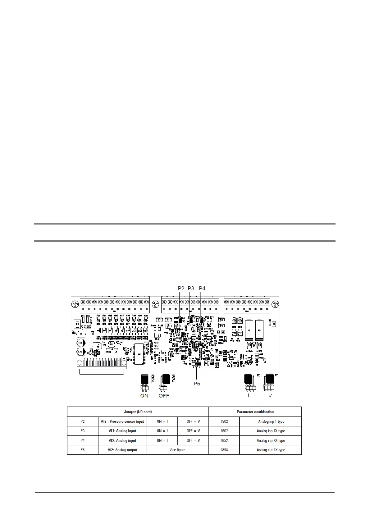
Note! If the pressure sensor signal is in current (i.e.. 4-10mA) is necessary to move the selection of Voltage/Current analog input
jumper in the I/O Board.
Here the I/O board jumper for the Analog I/O setting in Voltage/current (OFF = Voltage, ON = Current)
P2: Pressure sensor analog input AIS
P3: Analog Input AI1
P4: Analog Input AI2
P5: Analog Output AO
Figure 8: Analog Input Configuration