ADP200 Application PID-IMM User Manual Pag. 12 of 80
3.3 Single pump configuration via CANopen
With a single pump application (Par [11626] “CANMPActive= Off”) is possible to use the CANopen
interface to communicate between the Machine PLC and the drive (in this mode the drive is a Slave of the
CANopen Communication).
Note that in any case the Analog input for pressure feedback sensor is always necessary.
CANopen communication is enabled via parameter [4000] FieldBus Type in the menu
“COMMUNICATIONS/FIELDBUS CONFIG”. In the same menu you can select the BaudRate and the slave
address (see ADP200-FP manual for detail).
The example below shows a typical configuration, and an assignment of process data on a CANopen interface.
For digital input, the only fixed configuration is that to enable the drive the terminal EN HW must be 24V all the
other digital input should be done via CANopen (Control Word). For analog input, the sensor must be
connected to analog input all other reference can be done via CANopen.
Since process data are assigned in the parameters in the drive COMMUNICATION menu, the settings
described below are applicable regardless of the type of fieldbus used.
In Single Pump configuration process data are configured by the user via Gf-eXpress or Alphanumerical or
Local keypad or a dynamic mapping from master PLC (see example).
Machine
PLC
CANOPEN
FIELDBUS
L H
Gnd
GND
120ohm
ADP200
120ohm
Enable
Start
Fault Reset
Pressure
Sensor
Pressure
Feedback
9
8
70
71
72
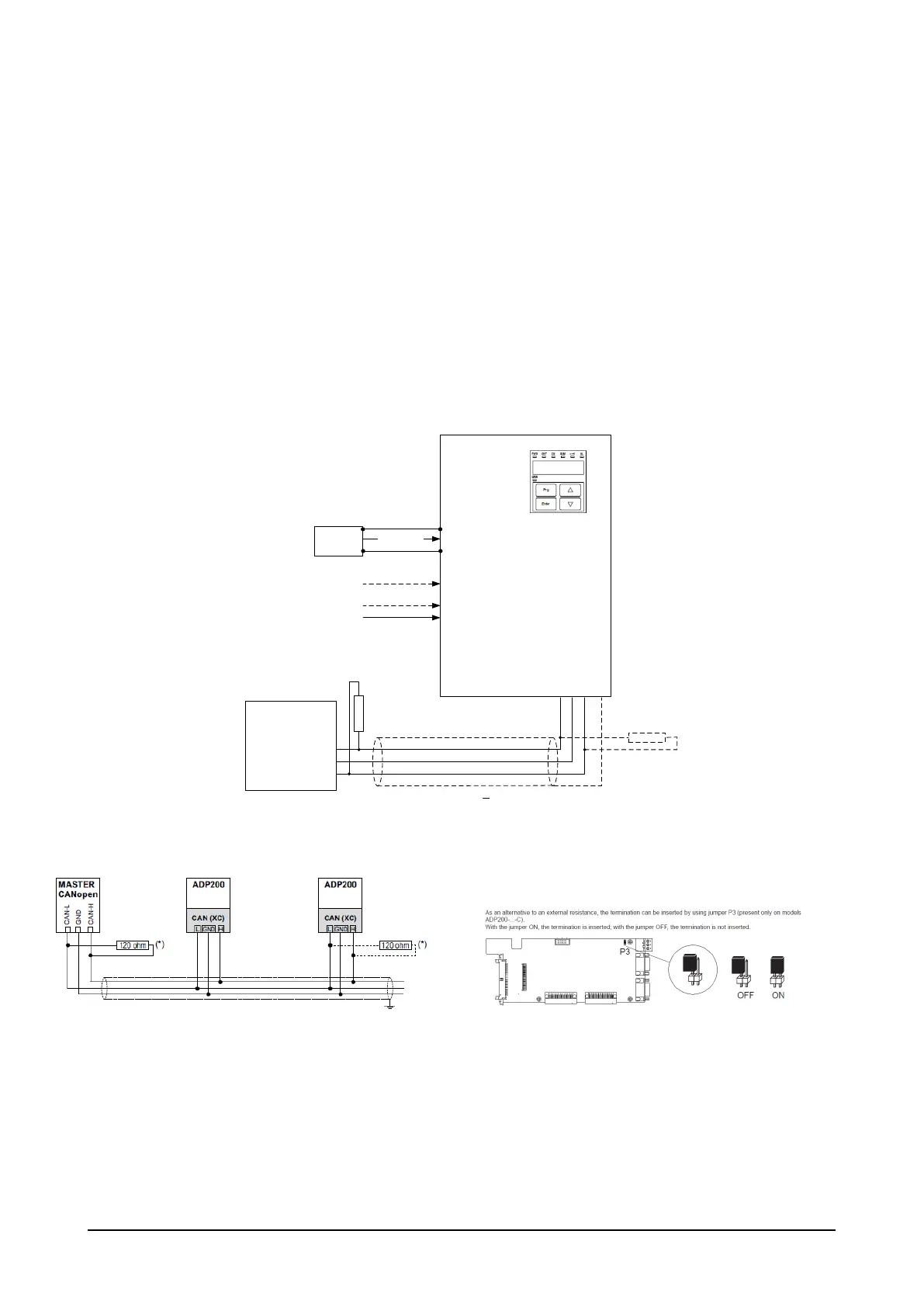
Figure 9: ADP200 CANopen PLC master Digital & Analog I/O connection
Figure 10: ADP200 with PLC CANopen master Bus Connection and termination
Typical I/O terminals (Regulation board + I/O expansion)
Digital Input (T1):
M9 = EN HW – (*) Enable (not programmable must be 24V if command done via control word)
M8 = DI1 – (*)Start (optional done with control word)
M6 = DI3 – (*)Fault Reset (Optional done with control word)