14 AGL50-EV
Use the following AC chokes to reduce the line current THD even more (< 35%).
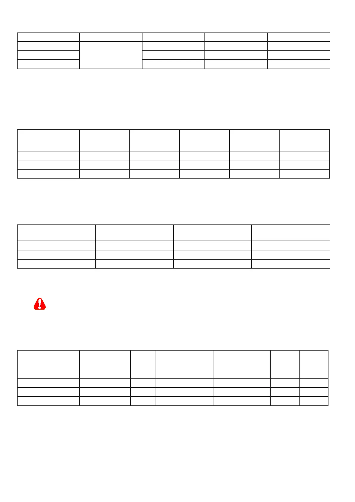
Sizes THD In @ 400 V [A] Type Code
2040
< 35%
8 LR3y-2040-35% S7HB1
2055 12 LR3y-2055-35% S7HB2
2075 15 LR3y-2075-35% S7FO9
Output chokes
Output chokes are used to reduce the effects of the dv/dt of the power modules (IGBT). Voltage fronts can damage the
electrical insulation of the motors or, if the motor cables are long (typically more than 100 m in length) or highly capaci-
tive, they can cause drive malfunctions and the repeated generation of overcurrent (OC) or desaturation (OCH) alarms.
The output chokes are listed in the table below:
Sizes
Mains
inductance
[mH]
Rated
current
[A]
Saturation
current
[A]
Type Code
2040 0.87 10.1 20 LU3-QX02 S7FL3
2055 0.87 16 34 LU3-005 S7FG3
2075 0.51 27 57 LU3-011 S7FG4
Internal braking unit
Internal braking units with external braking resistors (wired between terminals C and BR1) are used to prevent dangerous
DC link voltage levels in case of braking. Technical data of the internal braking unit (50% duty cycle)
Sizes Rated current
[Arms]
Peak current
[Apeak]
Minimum braking R value
[Ohm]
2040 5.7 8 100
2055 8.5 12 67
2075 8.5 12 67
Braking Resistors
The braking resistors can be subject to unforeseen overloads due to possible failures.
The resistors have to be protected using thermal protection devices. Such devices do not have to interrupt
the circuit where the resistor is inserted but their auxiliary contact must interrupt the power supply of the drive
power section. In case the resistor foresees the precence of a protection contact, such contact has to be used
together with the one belonging to the thermal protection device.
Recommended resistors for use with internal braking unit:
Sizes Resistor type Code
Max Overload
energy, 1”- duty-
cycle 10%
Max Overload
energy, 30”- duty-
cycle 25%
[kJ]
Pn cont
(*)
[W]
Rbr
[Ohm]
2040 RF 200 100R S8SA15 1.5 4 200 100
2055 RF 200 68R S8SA14 1.5 4 200 68
2075 RF 400 68R S8SA16 3.5 10 400 68
Resistors protection degree: IP44.
The braking resistor is optional and has always to be mounted externally.
(*) rated power with continuous operation. Without heat sink.
If the resistors are mounted on unpainted radiation plates (thermal resistance shown) the power ratings are
those shown in the table below. In overload conditions, heavier duty cycles can be set proportional to the
power ratings.

 Loading...


