AGL50-EV 17
4.4 Regulation Section
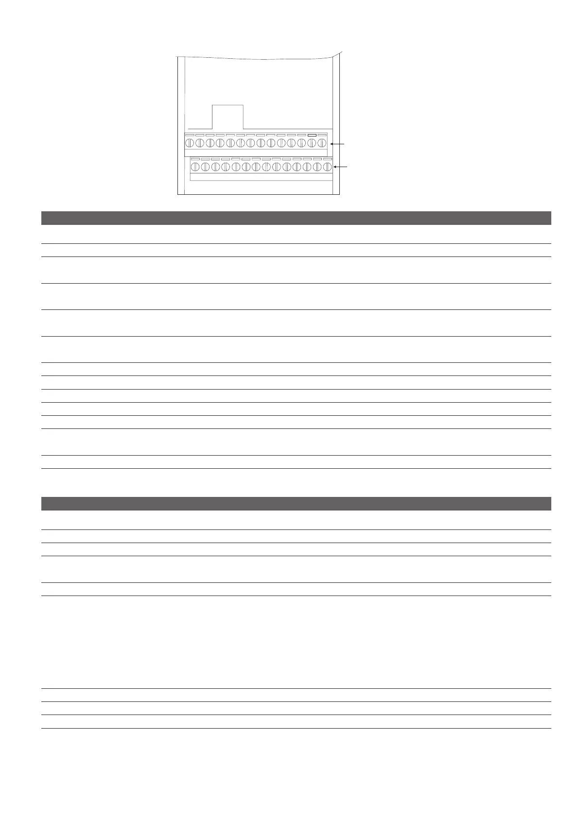
Strip1
Strip2
24
2
4
6
8
10
12
14
16
18
20
22 2826
23
1
3
5
7
9
11
13
15
17
19
21 2725
S T R I P 1
Term. Designation Function (Signal level MAX)
1/3 n.a.
5 Analog output 1 VOLTAGE programmable analog output (0...10V)
Default : I.300 = [0] Freq out abs (0...10V / 5mA)
7 + 10V OUT + 10 Vdc potential voltage reference
Default : n.a. (+10Vdc / 5mA, max 10mA)
9 - 10V OUT - 10 Vdc potential voltage reference
Default : n.a. (-10Vdc / 5mA, max 10mA)
11 Digital output 1+ Programmable digital output (Optomos)
Default : I100 = [51] Contactor (+30V / 40mA)
13 Digital output 1- Programmable OPEN COLLECTOR digital output (negative terminal)
15 RS485 Link+ Link+ (RxA / TxA) signal of RS 485 serial line
17 RS485 Link- Link- (RxB / TxB) signal of RS 485 serial line
19 RS 485 eq. ref. Equipotential reference of RS 485 serial line
21 COM Relay 1 Common contact RELAY 1 digital output (250Vac / 2A, 30Vdc / 2A)
23 Digital output 1 Programmable RELAY digital output, NO contact (250Vac / 2A, 30Vdc / 2A)
Default : I101 = [54] Brake cont
25 COM Relay 2 Common contact RELAY 2 digital output (250Vac / 2A, 30Vdc / 2A)
17 Digital output 2 Programmable RELAY digital output, NO contact (250Vac / 2A, 30Vdc / 2A)
Default : I102 = [02] No alarms
S T R I P 2
Term. Designation Function (Signal level MAX)
2/4 n.a.
6 COM analog. In/Out Potential reference of analog inputs/outputs -
8 Analog input 1 Programmable VOLTAGE analog input
Default : I.200 = [1] -10...+10V (±10V / 0.5mA)
10 0 V 24 0 V 24 potential reference
Programmable digital inputs (24Vdc/ 5mA, 12...30Vdc max)
12 Digital input 1 Default : I.000 = Enable src
14 Digital input 2 Default : I.001 = Run Fwd src
16 Digital input 3 Default : I.002 = Run Rev src
18 Digital input 4 Default : I.003 = Freq sel 1 src
20 Digital input 5 Default : I.004 = Freq sel 2 src
22 Digital input 6 Default : I.005 = Freq sel 3 src
24 COM Digital inputs 0 potential reference of digital inputs
26 0 V 24 0 V 24 potential reference
28 + 24V OUT + 24 Vdc potential voltage reference (+21Vdc / 75mA)
n.a. = not assigned

 Loading...


