AGL50-EV 13
4 - Wiring Procedure
4.1 Power Section
U1/L1, V1/L2, W1/L3 AC mains voltage (3 x 380 V (-15%) ... 3 x 480 V (+10%)
PE1 Mains ground connection (on terminal)
BR1 Braking unit resistor command (braking resistor must be connected between BR1 and C)
C, D Intermediate circuit connection
U2/T1, V2/T2, W2/T3 Motor connection
PE2 Motor ground connection (on chassis)
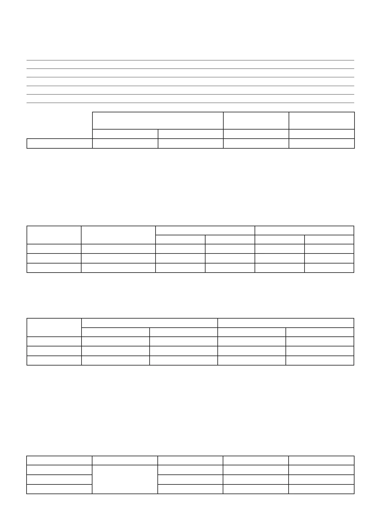
Maximum cable cross-section Recommended
stripping
Tightening
torque (min)
(mm
2
) (AWG) (mm) (Nm)
2040 - 2055 - 2075 4 (rigid) / 2.5 (exible) 12 8 0.5…0.6
Note!
Use 60°C / 75°C copper conductor only.
External fuses of the power section
The inverter must be fused on the AC Input side.
Use fast-acting fuses only. Use the fuses shown in the table below.
Connections with three-phase inductance on AC input will improve the DC link capacitors life time.
Sizes
DC link capacitor hours
of service life [h]
Europa America
Type Code Type Code
2040 10000 GRD2/20 F4D15 A70P20 S7G48
2055 10000 GRD2/25 F4D16 A70P30 S7I50
2075 10000 GRD2/25 F4D16 A70P30 S7I50
External fuses of the Power Section DC input side
Use fast-acting fuses only. Use the fuses shown in the table below.
Sizes
Europa America
Type Code Type Code
2040 GRD2/20 F4D15 A70P20 S7G48
2055 GRD2/25 F4D16 A70P30 S7I50
2075 GRD2/25 F4D16 A70P30 S7I50
Fuse manufacturers: Type GRD... , Z14... 14 x 51 mm Jean Müller, Eltville
A70... Ferraz
FWP... Bussmann
Input chokes
The three-phase mains choke is strongly recommended in order to:
- limit the RMS input current of the AGL50-EV inverter.
- increase the life of intermediate circuit capacitors and reliability of input diodes.
- reduce the harmonic distortion of the current absorbed by the grid to typical values of 70% (with rated current)
Sizes THD In @ 400 V [A] Type Code
2040
< 70 %
9 LR3y-2040 S7AAG
2055 13 LR3y-2055 S7AB5
2075 16 LR3y-2075 S7AB6

 Loading...


