18 AGL50-EV
4.5 RS 485 Serial Interface
The RS 485 serial line on the drives of the AGL50-EV series allows the data transmission through a loop made of two
symmetrical conductors, which are twisted with a common shield. The maximum transmission speed is 38400 Baud.
The transmission is performed via a standard RS 485 differential signal (half-duplex).
If two or more drives are connected on the serial line (Multidrop conguration), the OPT-QX option has to be used on each
device.
This option has to be inserted between the inverter terminals and the transmission data cable.
With the Multidrop conguration it is possible to connect a maximum of 20 units of AGL50-EV inverters (for further details
see the OPT-QX manual).
The shield of serial line cable must be connected to the ground.
4.5.1 RS485 serial terminals
The RS 485 serial line is supplied through 15, 17 and 19 terminals, placed on the regulation card of the inverter.
The differential signal is transmitted on the Pin 15 (TxA/RxA) and on the Pin 17 (TxB/RxB). Terminal 19 is used as
equipotential reference of the serial line.
Note!
As for the connection of the serial line, make sure that the power cables and the cables controlling the con-
tactors and the auxiliary relays are located into different panduits.
4.5.2 Serial protocol
The serial protocol is set via the “I.600 - Serial link cfg” parameter, which allows the selection of the following types:
proprietary protocol FoxLink, RTU Modbus (default) and Jbus.
The serial address is set via the “I.602 - Device address” parameter. Further details about the parameter transmission,
the parameter type and the value range can be found in the tables of Chapter 7.1 (INTERFACE Menu / Serial Conguration).
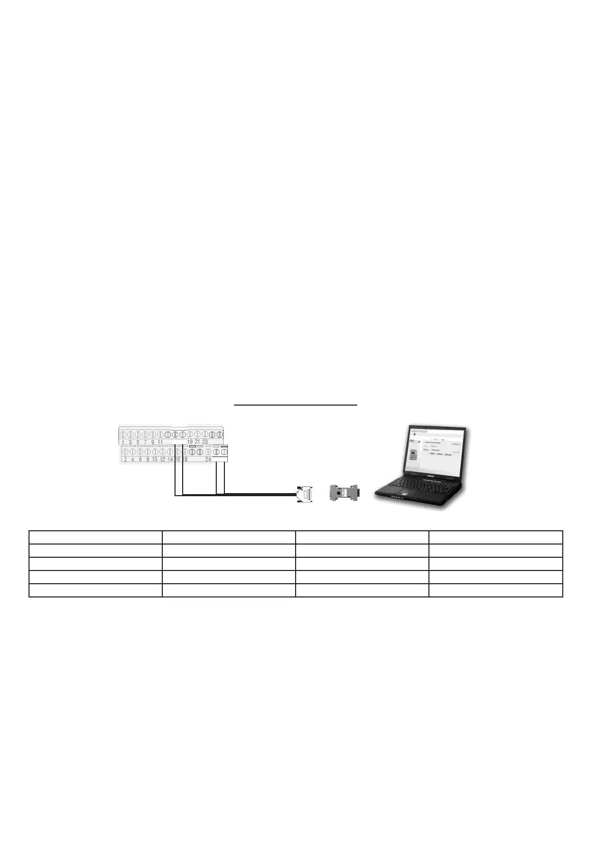
Figure 4.5.2.1: Serial Connections
XS1 - Drive Side
XS2 - PC Side
Giallo / Yellow
1
23
5
7
9
11
15
17
19
21
3
2
24
6
8
10
12
14
16
18
28
4
Cavo standard / Standard cable
cod. S7QAF9
Verde/Green
Bianco/White
Marrone/Brown
PCI-QX Interface
13
27
25
26
2220
PCI-QX Wire colour Signal AGL50-EV terminals
Pin 3 Yellow Link + 15
Pin 7 Green Link - 17
Pin 1 Brown + 24V Supply 28
Pin 8 White 0V Supply 26

 Loading...


